Transcription of WF-8900 Series
1 Operator's Manual WF-8900 Series WF-8935 | WF-8945 | WF-8955 | WF-8965 | WF-8975. ( The Power Center model number is located on the front panel label next to the breakers). Distributed in the and Canada by ARTERRA DISTRIBUTION. (877) 294-8997. Warranty: Fax (574) 294-8698. Power PROs Technical Support (877) 294-8997. TA B L E O F C O N T E N T S. SAFETY INFORMATION .. 3. GENERAL INFORMATION. Reverse Battery Protection .. 3. Blown Fuse Indicators .. 4. Automatic Cooling Fan .. 4. Over-Temperature Protection .. 4. Electronic Current Limiting .. 4. Short Circuit Protection .. 5. CIRCUIT PROTECTION. DC Fuses .. 5. AC Circuit Breaker.
2 5. UL-Listed Main Circuit Breaker List .. 5. UL-Listed Branch Circuit Breaker List .. 5. OPERATIONAL FEATURES. Three Stage Smart Charging .. 6. TROUBLESHOOTING INSTRUCTIONS. Converter Output voltage .. 7. Reverse Polarity Fuses .. 8. Troubleshooting Flow Chart .. 8. GENERAL COMPLIANCE INFORMATION. Agency Listings .. 9. INSTALLATION INSTRUCTIONS. Mounting the Enclosure ..10. Wiring the AC Breakers .. 10. Wiring the DC Fuse Board .. 11. SPECIFICATIONS .. 13. WARRANTY INFORMATION .. 14. 2. GENERAL INFORMATION. WF-8900 Series Power Center Safety Features Reverse Battery Protection The WF-8900 Series Power Centers will charge the 12-volt House battery if installed.
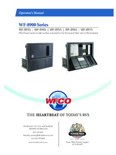
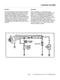
3 A battery DOES NOT have to be installed for WF-8900 Series Power Center converter operation. When a battery is installed, two reverse polarity fuses protect the converter circuitry. The fuses are located along the left-center edge of the DC fuse board below the VCC+ lug. Refer to Figure 1. below. This feature prevents permanent damage to the converter from a battery connected into the circuit backwards. In addition to protecting the converter section, the reverse polarity fuses are the main connection between the converter and the DC fuse board. 3. The fuse values and quantity vary depending on which WF-8900 Series Power Center you have.
4 Refer to the table and drawing below. WF-8935 40A (1) *NOTE: Only one of the two Reverse Polarity terminals is used. WF-8945 30A (2). WF-8955 40A (2). WF-8965 20A (4). WF-8975 20A (4). Figure 1. Blown Fuse Indicators on DC Fuse Board The DC Fuse Board has individual blown fuse indicators as standard equipment. Each of the 11 DC fuse circuits contain a Red LED to indicate a blown fuse. If one of the circuits draws more current than the rating of the fuse, the fuse will blow. When this occurs, the Red LED for that circuit will illuminate. NOTE: The fuse board employs surface mount LEDs which are barely visible to the naked eye.
5 Replace the blown fuse with a known good fuse of the same rating. NOTE: If the replacement fuse blows again, check that circuit for a short or overload condition. Automatic Cooling Fan The cooling fan in the WF-8900 Series Power Center is incremental and is controlled by the current drawn out of the converter to the applied load. The on-board microprocessor increases fan speed as the total load increases and decreases fan speed as the load decreases. Unlike traditional temperature-controlled fans, the load-controlled fan provides better component cooling by avoiding temperature spikes which can lead to premature component failure.
6 Over-Temperature Protection If the internal temperature of the converter exceeds a critical point, it will shut down. This protects the unit from excessive heat that may damage sensitive components. The unit will restart once the temperature inside has dropped. Electronic Current Limiting In the event that the output current exceeds the maximum rating for the WF-8900 Series Power Center converter, the output current will remain constant but the output voltage will begin to drop. If this occurs, the unit will recover once loads are reduced. 4. Short-Circuit Protection Should a short circuit occur in the RV, the WF-8900 Series Power Center converter will drop the voltage output to zero volts.
7 If the short-circuit condition is removed and no other fault conditions are detected, the converter will resume normal operation. However, short-circuit conditions are dangerous, and an RV will require inspection by a qualified service technician. CIRCUIT PROTECTION. WF-8900 Series Power Center Fuses and Breakers DC Fuses (12 Volts). The DC fuse board has spaces for eleven DC circuits. This includes two 30 Amp circuits (positions F10 and F11) to be used for slide-outs or other higher current loads. These circuits have a maximum rating of 30 Amps. The remaining nine circuits have a maximum 20 Amp rating. The circuit fuses and the Reverse Battery Protection fuses should be replaced with ATC or ATO automotive type fuses such as: Littelfuse type 257.
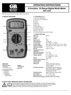
8 Bussmann type ATC. AC Circuit Breakers (120/240 Volts). The AC Breaker side of the WF-8900 Series Power Center is located on upper the left side. The WF-8900 Series Power Center accepts standard residential breakers. A total of ten breakers can be installed: one 30 Amp Main breaker and up to a maximum of nine AC. Branch circuits when using duplex breakers. A list of factory tested and approved breakers follows. The breakers may be purchased at most big-box department stores and home centers. UL-Listed Main Circuit Breakers, Rated for 120V, Maximum 30A. The following breakers have been factory tested and approved for use as 30 Amp Main breakers in the WF-8900 Series Power Center: Manufacturer Model/Cat.
9 Cutler Hammer Type BR and C. Thomas Betts Type TB or TBBD. ITE/Siemens Type QP or QT. Square D Type HOM or HOMT. Murray Type MP-T or MH-T. General Electric Type THQL. UL-Listed Branch Circuit Breakers, Rated for 120V, Maximum 20A. The following breakers have been factory tested and approved for use as Branch breakers in the WF-8900 Series Power Center: 5. Manufacturer Model/Cat. Cutler Hammer Type BR and C, Type BRD, BD and A. Thomas Betts Type TB or TBBD. ITE/Siemens Type QP or QT. Square D Type HOM or HOMT. Murray Type MP-T or MH-T. General Electric Type THQL. When replacing any of the installed circuit breakers, the replacement should be of the same manufacturer, type designation, and equal interrupting rating, not to exceed 30 A.
10 The Short-Circuit-Current rating for the breaker should be 10,000 Amps. Breaker Filler Plates: Model #FP-01 or FP-01B (Black). Figure 2. OPERATIONAL FEATURES. Converter Operation Modes Three-Stage Smart Charging In order to maximize battery life, it is best to charge batteries slowly, keep them topped off with a trickle-charge when the RV is not being used. The 3-Stage smart charger continuously measures the battery voltage output and regulates the amount of charge using three modes of operation; Absorption, Bulk and Float modes. All WFCO power converters are automatic three-stage switching power supplies. The converter senses which mode it needs to be in by checking the RV system voltage .