Transcription of WF12H, WF08H, WF06H, WF04H 0.1% Thick film …
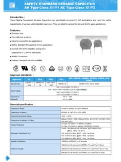
1 Approval sheet WF12H, WF08H, WF06H, WF04H . , Thick film high precision chip resistors Size 1206, 0805, 0603, 0402. *Contents in this sheet are subject to change without prior notice. Page 1 of 6 ASC_WFxxH_V02 Sep - 2011. Approval sheet FEATURE. 1. Small size and light weight 2. High reliability and stability 3. Reduced size of final equipment 4. High precision 5. Higher component and equipment reliability 6. RoHS compliant & Lead free products. APPLICATION. Power supply PDA. Digital meter Computer Palmtop computers DESCRIPTION. The resistors are constructed in a high grade ceramic body (aluminum oxide). Internal metal electrodes are added at each end and connected by a resistive paste that is applied to the top surface of the substrate. The composition of the paste is adjusted to give the approximate resistance required and the value is trimmed to nominated value within tolerance which controlled by laser trimming of this resistive layer.
2 The resistive layer is covered with a protective coat. Finally, the two external end terminations are added. For ease of soldering the outer layer of these end terminations is a Tin (lead free) alloy. Fig 1. Construction of Chip-R. Page 2 of 6 ASC_WFxxH_V02 Sep - 2011. Approval sheet QUICK REFERENCE DATA. Item General Specification Series No. WF12H WF08H WF06H WF04H . Size code 1206 (3216) 0805 (2125) 0603 (1608) 0402 (1005). Resistance Range 10 ~ 1M ( E96+E24 series). Resistance Tolerance , TCR (ppm/ C) 10 R 1M 100 ppm/ C. Max. dissipation at Tamb=70 C 1/4 W 1/8 W 1/10 W 1/16W. Max. Operation Voltage (DC or RMS) 200V 150V 50V 50V. Max. overload voltage (DC or RMS) 400V 300V 100V 100V. Climatic category 55/155/56. Note : 1. This is the maximum voltage that may be continuously supplied to the resistor element, see IEC publication 60115-8.
3 2. Max. Operation Voltage : So called RCWV (Rated Continuous Working Voltage) is determined by RCWV = Rated Power Resistance Value or Max. RCWV listed above, whichever is lower. 3. Non E96 series resistance upon requested. DIMENSIONS(unit : mm). Part No WF12H WF08H WF06H WF04H . L W Tt Tb T MARKING. 3-digits marking for 0603 size WFxxH has same marking rule as WRxx 1%. 4-digits marking for 1206, 0805 size Each resistor is marked with a four digits code on the protective coating to designate the nominal resistance value. For values below 97 6 the R is used as a digit. For values of 100 or greater, the first 3 digits are significant, the fourth digit indicates the number of multiple to follow. Example RESISTANCE 10 12 100 6800 47000 . 4-digits marking 10R0 12R0 1000 6801 4702. No marking code for 0402 size Page 3 of 6 ASC_WFxxH_V02 Sep - 2011.
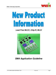
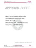
4 Approval sheet FUNCTIONAL DESCRIPTION. Product characterization Standard values of nominal resistance are taken from the E96 & E24 series for resistors with a tolerance of , The values of the E24/E96 series are in accordance with IEC publication 60063 . Derating The power that the resistor can dissipate depends on the operating temperature; see Figure 2. Maximum dissipation in percentage of rated power As a function of the ambient temperature SOLDERING CONDITION. The robust construction of chip resistors allows them to be completely immersed in a solder bath of 260 C for 10 seconds. Therefore, it is possible to mount Surface Mount Resistors on one side of a PCB and other discrete components on the reverse (mixed PCBs). Surface Mount Resistors are tested for solderability at 235 C during 2 seconds. The test condition for no leaching is 260 C for 30 seconds.
5 Typical examples of soldering processes that provide reliable joints without any damage are given in Fig 3. Fig 3. Infrared soldering profile for Chip Resistors CATALOGUE NUMBERS. The resistors have a catalogue number starting with : WF06 H 3742 D T L. Size code Type code Resistance code Tolerance Packaging code Termination code WF12 : 1206 H : High precision, E96+E24: D : T : 7 Reeled taping L = Sn base (lead <1%, TCR>50ppm free). WF08 : 0805 3 significant digits followed B : by no. of zeros WF06 : 0603. 102 =1020. WF04 : 0402. =3742. 220 =2200. Reeled tape packaging : 8mm width paper taping 5000pcs per 7 reel for 1206/0805/0603, 10000pcs per 7 reel for 0402. Page 4 of 6 ASC_WFxxH_V02 Sep - 2011. Approval sheet TEST AND REQUIREMENTS(JIS C 5201-1 : 1998). TEST PROCEDURE REQUIREMENT. DC resistance DC resistance values measured at the test voltages specified below : Within the specified tolerance Clause <10 <100 <1K <10K @3V, <100K @10V, <1M @25V, <10M Temperature Natural resistance change per change in degree centigrade.
6 Refer to Coefficient of R2 R1 QUICK REFERENCE DATA . Resistance( ) 106. Clause R1 (t2 t1 ) (ppm/ C) ; t1 : 20 C+5 C-1 C. R1 : Resistance at reference temperature R2 : Resistance at test temperature Short time overload Permanent resistance change after a 5second application of a voltage R/R max. ( + ). ( ) times RCWV or the maximum overload voltage specified in the Clause above list, whichever is less. Resistance to soldering Un-mounted chips completely immersed for 10 1second in a SAC no visible damage heat( ) solder bath at 260 5 C. Clause R/R max. ( + ). Solderability Un-mounted chips completely immersed for 2 second in a SAC good tinning (>95% covered). Clause solder bath at 235 5 . no visible damage Temperature cycling 30 minutes at -55 C 3 C, 2~3 minutes at 20 C+5 C-1 C, 30 minutes no visible damage at +155 C 3 C, 2~3 minutes at 20 C+5 C-1 C, total 5 continuous Clause R/R max.
7 ( + ). cycles Load life (endurance) 1000 +48/-0 hours, loaded with RCWV or Vmax in chamber controller R/R max. (1%+ ). Clause 70 2 C, hours on and hours off Load life in Humidity 1000 +48/-0 hours, loaded with RCWV or Vmax in humidity chamber R/R max. (1%+ ). Clause controller at 40 C 2 C and 90~95% relative humidity, on and hours off Bending strength Resistors mounted on a 90mm glass epoxy resin PCB(FR4); R/R max. ( + ). Clause bending : 3 mm, once for 10 seconds Adhesion Pressurizing force: 5N, Test time: 10 1sec. No remarkable damage or Clause removal of the terminations. Insulation Resistance Apply the maximum overload voltage (DC) for 1minute R 10G . Clause Dielectric Withstand Apply the maximum overload voltage (AC) for 1 minute No breakdown or flashover Voltage Clause Page 5 of 6 ASC_WFxxH_V02 Sep - 2011.
8 Approval sheet PACKAGING. Paper Tape specifications (unit :mm). Series No. A B W F E. WF12H WF08H WF06H WF04H Series No. P1 P0 D T. WF12H WF08H + WF06H WF04H Reel dimensions Symbol A B C D. (unit : mm) Taping quantity - Chip resistors 5,000 pcs/reel for WF12H, WF08H, WF06H. - Chip resistors 10,000 pcs/reel for WF04H . Page 6 of 6 ASC_WFxxH_V02 Sep - 2011.