Transcription of WF448 Front Load Washer Training Manual
1 1WF448 Front load Washer Large Capacity ( Cu. Ft.) Vibration Reduction Technology Steam Wash/Steam Dry (VRT team ) SilverCare Technology Energy-Efficient : MEF course will describe the features, service modes, testing and troubleshooting changes of the new large capacity Front load washer22 Model Number NomenclatureModel number nomenclature for the Purple project showing how to read the number to be able to tell which features and color the model Product FeaturesNew features for 2008 are a larger capacity, steam, VRT and silver care. The VRT and SilverCare features have been used successfully in the previously marketed models442008 - 2007 Model ComparisonCompared to the top end model from 2007, the 2008 model has many new features including a newly designed drum that is gentler on the laundry during the high speed and Service ModesThere are several test and service modes to help the technician troubleshoot and diagnose various problems in the laundry products. This module will explain how to enter these modes and what tests can be Test ModeEnter the Quick Test Mode by pressing the soil level, signal and power buttons at the same timeEnter the Quick Test Mode by pressing the soil level, signal and power buttons at the same time77 Quick Test ModeIn the quick test mode there are 4 different tests that can be performed through the on board diagnostics.
2 In this mode if the cycle selector dial is turned to indicate "spin" and then the start button is pressed, the technician or installer can go to the quick spin mode which is the high spin drum test. This is necessary for the installer to test level and balance and for the technician to test the Valve CheckIn the quick test mode with every press of the temp key a different water valve will be activated until after the last valve and then the temp key will cancel the CheckWhen testing the heaters you will hear the relay clicking to indicate the heater is on and the 120 VAC can be measured as are 2 heaters in this machine . One for the steam feature and one for the sanitize wash cycle. In the quick test mode press the signal key to first turn on the water heater and then the steam heater and once again to cancel the Lock CheckTo check the door lock from the quick test mode press the spin key and check the function of the lock CheckThere are 2 pumps in the purple Washer .
3 A drain pump and a circulation pump. They can both be tested by pressing the soil level key in the quick test mode. 1212 Service ModeThe service mode is entered with the power on and pressing the signal and extra rinse buttons service mode is entered with the power on and pressing the signal and extra rinse buttons Time DownTo enter the fast time down mode, press the temp button in the service modeIn the service mode press the temp button and the machine will go into a mode the resembles a complete wash cycle in a fraction of the time it would normally take. Every water valve and motor will be used to check Selector TestIn the service mode press the extra wash buttonCycle selector positionPress StartTest item Extra Rinse LED On Measure internal water temperatureExtra Spin LED On Door status (open/close)Delay Start LED On Door lock status (lock/unlock)My Cycle LED On Silver care board In the service mode press the extra wash button to test, among other items, the temperature of the water in the tub, the status of the door - open/closed and locked/unlocked and the condition of the silver care Code CheckIn the service mode press the silver care button until there is a flashing "d" on the LCD display.
4 Turn the cycle selector dial either way and if there are any stored codes they will be displayedThe Washer retains 9 diagnostic codes in memory that can be retrieved. In the service mode press the silver care button until there is a flashing "d" on the LCD display. Turn the cycle selector dial either way and if there are any stored codes they will be displayed. For an understanding of these code refer to the error code section of the service Manual . Also in the diagnostic code check mode the cycle count of complete wash cycle can be seen by pressing the signal button and the cycle count and diagnostic codes can be cleared by pressing the delay start and signal buttons for 3 VRT TechnologyVRT or Vibration Reduction Technology is a simple but effective way of counter balancing the load inside the wash presentation will explain the Vibration Reduction Technology feature in the new Front load washing Theory of OperationConventionalSamsungHowever it takes some time before they are in a position of balance.
5 Until the drum speed reaches approximately 300 RPM the drum will seem to be out of steel balls will find their balanced position based on the weight of the wash load with VRTW ithout VRT the wash load is hard to balanceSeen in this animation is the mathematical equations behind the principal of the VRT system. The steel balls will find their "sweet spot" based on the weight of the wash load . However it takes some time before they are in a position of balance. Until the drum speed reaches approximately 300 RPM the drum will seem to be out of the VRT SystemEnter the "Quick Test Mode", turn the cycle selector to "Spin" and press the "Start/Pause" buttonTo test the VRT for balance, place approximately 1lb of wet towels into the drum. Put the machine into the quick test mode by pressing the "soil level", "Signal" and "Power " buttons simultaneously. Move the cycle select dial to indicate "Spin" in the LCD display and press the Start/Pause button. The drum will go into the high speed spin and after about 300 RPM will become Drum MotorOperation, troubleshooting and replacement procedureThis module will explain the operation, testing and troubleshooting and replacement of the rotor and stator combination drum Motor CircuitVoltage input to motorFeed back from Hall sensorThe drum motor receives voltage to the windings of the stator from the main board.
6 Depending on the speed of the motor different windings will be supplied with the necessary voltage to increase or decrease the speed of the motor including electronic braking. The Hall sensor supplies feedback to the main board to indicate that the motor is moving, what direction the motor is moving and how fast the motor is rotating. The main board then takes this data and converts it to read RPM on the LCD display in the service mode. The Hall sensor is also used for detecting unbalanced the Drum MotorThe red, white and blue wires go directly from CN5 to the stator of the drum Windings Check:Resistance at Pin #1 and #2 of CN5 = 12 Resistance at Pin #1 and #3 of CN5 = 12 Resistance at Pin #2 and #3 of CN5 = 12 CN 51 2 3 Drum MotorMain BoardThe red, white and blue wires go directly from CN5 to the stator of the drum motor. The resistance or continuity of the stator windings and the wiring harness can be checked together by measuring the resistance from the Main Motor Rotor RemovalRemove the rear access panel to uncover the drum motorAfter removing the rear access panel, slide a Philips screw driver into a hole in the rotor and through a stator winding.
7 This will keep the rotor from spinning the drum when loosening the nut. Using a 19mm wrench or socked, remove the retaining nut and Washer . Care must be taken to prevent the screwdriver from damaging the stator windings. With both hands remove the rotor from the drum shaft. The splined shaft the strong magnetic pull of the rotor will make this a somewhat difficult task. Reassembly is the reverse procedure but watch your fingers don't get pinched when the rotor pulls itself onto the shaft due to the strong magnetic Motor Rotor RemovalSlide a Philips screw driver into a hole in the rotor and through a stator winding. This will keep the rotor from spinning the drum when loosening the nut. Using a 19mm wrench or socked, remove the retaining nut and washerAfter removing the rear access panel, slide a Philips screw driver into a hole in the rotor and through a stator winding. This will keep the rotor from spinning the drum when loosening the nut. Using a 19mm wrench or socked, remove the retaining nut and Washer .
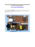
8 Care must be taken to prevent the screwdriver from damaging the stator windings. With both hands remove the rotor from the drum shaft. The splined shaft the strong magnetic pull of the rotor will make this a somewhat difficult task. Reassembly is the reverse procedure but watch your fingers don't get pinched when the rotor pulls itself onto the shaft due to the strong magnetic Motor Stator RemovalRemove the 6 - 10mm bolts that secure the stator to the rear tub sectionWith the rotor removed, remove the 6 - 10mm bolts that secure the stator to the rear tub section. Carefully remove the 2 connectors from the stator first. Reassembly is the reverse ValvesHOT COLDThis module will explain the water valve operation and function. Valve 1 is the hot water connection, valve 2 is the pre wash cycle cold water valve, valve 3 is the bleach cycle valve, valve 4 is the main wash cold water valve and valve 5 is cold water valve for the steam Valve Relay CircuitRY5 - Bleach water valveRY6 - Steam water valveRY11 - Pre wash water valveRY12 - Main cold water valveRY13 - Main hot water valveCN 3 pin 1 - Pink wire - Bleach valveCN 3 pin 2 - Brown wire - Steam valveCN 3 pin 7 - Yellow wire - Pre wash valveCN 3 pin 8 - Blue wire - Main cold valveCN 3 pin 9 - Red wire - Main hot valve2727 Checking the Water ValvesEnter into the "Quick Test" mode and press the Temp buttonOnce in the quick test mode with every press of the temp button, a different water valve will the Water Water Valve CheckCheck the Voltage at Pin #1 of CN2 and Pin #1, 2, 7.
9 8 and 9 of CN3 When each valve operates the measured voltage is 120 VAC When checking the resistance of the water valve solenoids they should all measure approximately 5 Checking the voltage to the water valves should measure 120 VAC. When measuring the resistance of the valve solenoid at the valve, disconnect the electrical connector and the coil windings should read about 5 2929 Replacing the Water ValvesHOTCOLDThe hot water valve is a single valve and the cold valve is a quad valveTo replace a defective cold water valve all four are replaced as a unit. The hot water valve is replaced independent of the cold water valves. Start by making sure the power is removed from the machine . Remove the top cabinet panel and disconnect the electrical connector(s) from the valve body. When disconnecting the water valves it is important that the correct connector be returned to the correct valve or the wash cycles will not have the proper water valve opening when called the Water ValvesHOTCOLDA fter the electrical connections are removed, remove the screws from the defective valve body.
10 Next disconnect the water hoses going to the detergent drawer and remove the valve. Assemble in the reverse and Circulation PumpDRAINCIRCULATIOND rain HoseWater inlet from tubCirculation water out to tubDrain pump and circulation pump operation, troubleshooting and diagnosis and replacementThis module will explain the drain pump operation and some troubleshooting tips as well as the procedure for and Circulation Pump CircuitRY 7 controls the drain pump and RY 10 controls the circulation pumpRY 10 controls the circulation pump and RY 7 controls the drain pump. IC 4 and 5 act a buffers between the relay circuits and the main processor or MICOM that controls all functions of the machine . Low voltage and current circuits switching high voltage and current devices on and the Drain and Circulation PumpsTo check the Drain Pump operation, press the Soil Level Key while model information is being displayed during the Quick Test check the Drain Pump operation, press the Soil Level Key while model information is being displayed during the Quick Test the Drain and Circulation PumpsCirculation Drain Drain Motor CheckCheck the voltage at Pin #1 (common blue wire) of CN2 and Pin #3 (violet wire) of CN3 When Drain Motor operates = AC 120 VCirculation Motor CheckCheck the voltage at Pin #1 (common blue wire) of CN2 and Pin #6 (gray wire) of CN3 When Circulation Motor operates = AC 120 VIf the pumps are not operating properly, check the voltage from the main board to the pumps.