Transcription of WHAT MAKES A CRITICAL ENGINE CRITICAL? (CLASSICAL …
1 WHAT MAKES . A. CRITICAL ENGINE CRITICAL ? (CLASSICAL VERSION). Part 1 of 14 CFR (the FAR's) defines the term CRITICAL ENGINE in these terms: CRITICAL ENGINE means the ENGINE whose failure would most adversely affect the performance and handling qualities of an aircraft. Naturally, the aircraft mentioned in this definition is understood to be a multiengine airplane. Although no further explanation is provided in Part 1, applicants for Airplane Multiengine ratings are required to provide details of CRITICAL ENGINE dynamics in the oral portion of the practical test, as indicated in the following excerpt from the Private Pilot and Commercial Pilot Practical Test Standard: I.
2 AREA OF OPERATION: PREFLIGHT PREPARATION. H. TASK: PRINCIPLES OF FLIGHT ENGINE INOPERATIVE. (AMEL and AMES). REFERENCES: FAA-H-8083-3, AC 61-23/FAA-H-8083-25; POH/AFM. Objective. To determine that the applicant exhibits knowledge of the elements related to ENGINE inoperative principles of flight by explaining the: 1. meaning of the term CRITICAL ENGINE .. 2. effects of density altitude on the VMC demonstration. 3. effects of airplane weight and center of gravity on control. 4. effects of angle of bank on VMC. 5. relationship of VMC to stall speed. 6.
3 Reasons for loss of directional control. 7. indications of loss of directional control. 8. importance of maintaining the proper pitch and bank attitude, and the proper coordination of controls. 9. loss of directional control recovery procedure. 10. ENGINE failure during takeoff including planning, decisions, and single- ENGINE operations. Effective discussion of elements 1 and 6 (author's bold print) above requires a complete working knowledge of the dynamics involved. Commercially-available texts offer coverage of this subject that is disorganized, incomplete, or (in some cases) erroneous.
4 The goal of this article is to provide multiengine students with a properly-organized, accurate, and easily-understood discussion of CRITICAL ENGINE dynamics that will enable them to quickly and correctly deal with this subject on the practical test. Offered here is the conventional explanation of CRITICAL ENGINE dynamics. While it contains some disturbing inconsistencies, discussion in these terms will satisfy the elements in the practical test standard. Additionally, the explanation presented here is valid to a conventional multiengine airplane, where both propellers rotate in a clockwise direction (as viewed from the rear).
5 The elements involved a discussion of CRITICAL ENGINE mechanics are commonly committed to memory using the mnemonic acronym PAST: P-factor, Accelerated slipstream, Spiraling slipstream, and Torque. P-FACTOR, more properly called asymmetrical disc loading, is a phenomenon that occurs when an airplane is flown a high angle of attack, as would be the case of a multiengine attempting to maintain altitude or climb when being flown single- ENGINE . As every student pilot knows (or SHOULD know), the descending blade of the propeller is operating at a much higher angle of attack than the ascending blade.
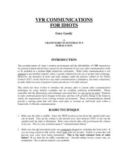
6 This shifts the center of thrust to the right of the propeller hub, as illustrated in Figure 1. Rotational Force Vector L . Rotational Force Vector R . Center Center of of Thrust Thrust Center of Gravity Lever Arm B Lever Arm A . Figure 1. In this figure, the relative amounts of thrust generated by the propellers operating at a high angle of attack are represented by the blue vector arrows. When these force vectors are averaged, the result is the centers of thrust, depicted by the green vector arrows. The dashed green lines demonstrate the lever arms from the center of gravity to the centers of thrust.
7 The same amount of thrust is generated by each ENGINE , but, since Lever Arm A is longer that Lever Arm B , then the yawing force to the left provided by the right propeller (Rotational Force Vector L ) is greater than the yawing force to the right (Rotational Force Vector R . The conclusion is: the pilot's ability to generate enough rudder effectiveness to control yaw is diminished with the loss of the thrust from the left ENGINE compared to the opposite condition. Flight characteristics of the airplane that are associated with P-factor directly impact YAW.)
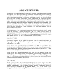
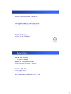
8 Control in single- ENGINE operations. ACCELERATED SLIPSTREAM is an adverse rolling phenomenon that is the result of P- factor. As shown in Figure 2, when the center of thrust shifts right as angle of attack is increased, the accelerated air behind the propeller shifts in a similar fashion. Center Center of of Thrust Thrust Center of Gravity Vectors of Accelerated Slipstream Figure 2. Since Bernoullian lift is airspeed-dependent, the center of lift shifts in the direction of the greater accelerated slipstream, as illustrated in Figure 3, as viewed from the rear of the airplane.
9 Rotational Roll Vector L . Rotational Roll Vector R . Lateral Center of Lift Lift Vectors Lever Arm B Lever Arm A . Figure 3. The lateral centers of lift produce rolling moments around the center of gravity. Since the right center of lift acts at a longer lever arm, A , its rotational force vector, L , is greater than rotational force vector R generated by the left ENGINE /propeller. Therefore, the left ENGINE meets the definition of CRITICAL because its loss would result in an airplane whose control around its roll axis would be limited to the greatest degree.
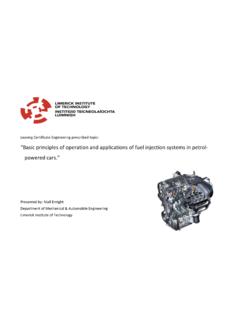
10 Flight characteristics of the airplane that are associated with accelerated slipstream directly impact ROLL control in single- ENGINE operations. The traditional view of the subject of SPIRALLING SLIPSTREAM maintains that, as a spinning propeller creates thrust, it imparts a spin to the airflow behind it. The coriolis effect causes this spiralling slipstream to be displaced laterally. In conventional multiengine airplanes with engines rotating clockwise (when viewed from the rear), that displacement is to the left, as illustrated in Figure 4 below: Figure 4.