Transcription of WHEEL ALIGNMENT SPECIFICATIONS & PROCEDURES
1 WHEEL ALIGNMENT SPECIFICATIONS & PROCEDURES For 1234 1992 WHEEL ALIGNMENT Subaru SPECIFICATIONS & PROCEDURES Justy, Legacy, Loyale, SVX * PLEASE READ THIS FIRST *NOTE: Prior to performing WHEEL ALIGNMENT , perform preliminary visual and mechanical inspection of wheels, tires and suspension components. See PRE- ALIGNMENT INSTRUCTIONS in WHEEL ALIGNMENT THEORY & OPERATION article in the WHEEL ALIGNMENT Section WHEEL ALIGNMENT PROCEDURES CAMBER ADJUSTMENT Justy (Front & Rear) Camber and caster are not adjustable. If measurements are notwithin SPECIFICATIONS , check for frame damage, transverse link damage,or worn out components (struts/springs, ball joint, etc.). Legacy & SVX (Front) Loosen both lower strut mounting bolts so strut can Fig. 1. Turn strut adjusting bolt to adjust camber. Strutadjusting bolt has eccentric cam head to force strut to positive ornegative camber adjustment.
2 Tighten bolts to specification . See TORQUESPECIFICATIONS table at end of 1: Adjusting Front Camber (Legacy & SVX)Courtesy of Subaru of America, Inc. Legacy & SVX (Rear) Camber is not adjustable. If camber measurement is not withinspecification, check for frame damage, lateral link damage or worn outcomponents (struts/springs, joints, etc.). Loyale (Front) Camber and caster are not adjustable. If measurements are notwithin SPECIFICATIONS , check for frame damage, transverse link damage,or worn out components (struts/springs, ball joint, etc.). Loyale (Rear) 1) Remove WHEEL . Remove lower shock bolt at inner arm (ifnecessary). Loosen outer arm mounting bolts. See Fig. 2. If camberangle measurement is too positive, use a lever to increase angle "0"between inner arm and outer arm. See Fig. 2: Adjusting Rear Camber & Toe-In (Loyale)Courtesy of Subaru of America, Inc.
3 2) If camber angle measurement is too negative, use lever todecrease angle "0" between inner arm and outer arm. Changing camberangle will change toe-in measurement. Changing toe-in will changecamber angle. Tighten outer arm mounting bolts to 94-108 ft. lbs.(127-147 ). CASTER ADJUSTMENT All Models (Front) Caster is not adjustable. If measurement is not withinspecification, check for frame damage, transverse link damage, or wornout components (struts, ball joint, etc.). TOE-IN ADJUSTMENTWHEEL ALIGNMENT SPECIFICATIONS & PROCEDURES Article Text (p. 3) All Models (Front) 1) Ensure tires are inflated to specification . Ensure ridingheight and normal riding load are set. Lock steering WHEEL tostraight-ahead center position. 2) Loosen both tie rod lock nuts. Turn both tie rods equalamounts until within toe-in SPECIFICATIONS . See WHEEL ALIGNMENTSPECIFICATIONS table at end of article.
4 Tighten lock nuts tospecification. See torque SPECIFICATIONS table at end of article. Justy (Rear) 1) Ensure tires are inflated to specification . Ensure ridingheight and normal riding load are set. Release parking brake. Loosentrailing link mounting bolt one turn. See Fig. 3: Measuring Riding Height & Adjusting Rear Toe-In (Justy)Courtesy of Subaru of America, Inc 2) Turn cam bolt 2 scale notches in opposite direction ofrequired adjustment in order to remove any free play. Slowly turn cambolt back in adjusting direction until correct toe-in specification isachieved. Tighten cam bolt to 44-51 ft. lbs. (59-69 ). Legacy 2WD (Rear) Loosen adjusting bolt on rear lateral link. See Fig. 4. Usingspanner WHEEL wrench, turn adjusting WHEEL counter-clockwise to changetoe-in angle. Turn adjusting WHEEL clockwise to change toe-out adjusting bolt to 87-116 ft. lbs. (118-157 ).
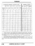
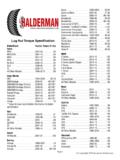
5 Fig. 4: Adjusting Rear Toe-In (Legacy & SVX)Courtesy of Subaru of America, Inc. Legacy 4WD & SVX (Rear) Loosen adjusting bolt for rear lateral link. See Fig. 4. TurnWHEEL ALIGNMENT SPECIFICATIONS & PROCEDURES eccentric cam bolt head counterclockwise to change toe-out angle. Turneccentric cam bolt head clockwise to change toe-in angle. Tightenadjusting bolt to 61-83 ft. lbs. (83-113 ). Loyale (Rear) 1) Remove WHEEL . Loosen outer arm mounting bolts. See Fig. toe-in is excessive, push/pull rear axle toward rear of vehiclewhile tightening outer arm mounting bolts. 2) If toe-out is excessive, push/pull rear axle toward frontof vehicle while tightening outer arm mounting bolts. Changing toe-inwill change camber angle. Changing camber angle will change toe-inmeasurement. Tighten outer arm mounting bolts to 94-108 ft. lbs. (127-147 ). torque SPECIFICATIONSTORQUE SPECIFICATIONS TABLE Application Ft.
6 Lbs. ( )Front Strut Camber Adjusting Bolts Legacy & SVX .. 97-127 (132-172)Rear Trailing Link Cam Bolt (Justy) .. 44-51 (59-69)Tie Rod Lock Nuts Justy .. 36-47 (49-64) Loyale, Legacy & SVX .. 58-65 (79-88) WHEEL Lug Nuts (All) .. 58-72 (79-98) WHEEL ALIGNMENT SPECIFICATIONSWHEEL ALIGNMENT SPECIFICATIONS TABLE Application Preferred RangeJusty Camber (1) Front .. To Rear .. 0 .. -1 To 1 Caster (1) .. To Toe-In (2) Front .. (2) .. To (1 To 3) Rear .. 0 (0) .. To (-3 To 3) Toe-In (1) Front .. To Rear .. 0 .. To Sedan 2WD Camber (1) Front .. To Rear .. -1 .. -2 To 0 Caster (1) .. To Toe-In (2) Front .. 0 (0) .. To (-3 To 3) Rear.
7 0 (0) .. To (-3 To 3) Toe-In (1) Front .. 0 .. To Rear .. 0 .. To Sedan 4WD Camber (1) Front .. 0 .. To Rear .. -1 .. -2 To 0 Caster (1) .. 3 .. 2 To 4 Toe-In (2) Front .. 0 (0) .. To (-3 To 3) Rear .. 0 (0) .. To (-3 To 3) Toe-In (1) Front .. 0 .. To Rear .. 0 .. To Wagon 2WD Camber (1) Front .. To Rear .. To Caster (1) .. To Toe-In (2) Front .. 0 (0) .. To (-3 To 3) Rear .. 0 (0) .. To (-3 To 3) Toe-In (1) Front .. 0 .. To Rear .. 0 .. To Wagon 4WD Camber (1) Front .. 0.
8 To Rear .. To Caster (1) .. To Toe-In (2) Front .. 0 (0) .. To (-3 To 3) Rear .. 0 (0) .. To (-3 To 3) Toe-In (1) Front .. 0 .. To Rear .. 0 .. To Sedan 2WD Camber (1) Front .. 0 To Rear .. 0 .. To Caster (1) .. To Toe-In (2) Front .. (2) .. To (1 To 3) Rear .. 0 (0) .. To (-2 To 2) Toe-In (1) Front .. To Rear .. 0 .. To Wagon 2WD Camber (1) Front .. 1 .. To Rear .. 0 .. To Caster (1) .. To Toe-In (2) Front .. (2) .. To (1 To 3) Rear .. 0 (0) .. To (-2 To 2) Toe-In (1) Front.
9 To Rear .. 0 .. To 4WD Camber (1) Front .. To Rear .. 0 .. To Caster (1) .. Toe-In (2) Front .. (-5) .. To (-6 To -4) Rear .. 0 (0) .. To (-2 To 2) Toe-In (1) Front .. To Rear .. 0 .. To Camber (1) Front .. To Rear .. To Caster (1) .. To Toe-In (2) Front .. 0 (0) .. To (-3 To 3) Rear .. 0 (0) .. To (-3 To 3) Toe-In (1) Front .. 0 .. To Rear .. 0 .. To (1) - Measurement is in degrees.(2) - Measurement is in inches (mm).