Transcription of When is a Balun, not a balun, when it is an UNUN
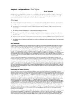
1 The balun and The unun - page 1 when is a balun , not a balun , when it is an unun ! balun = "BALanced-to-UNbalanced" unun = "UNbalanced-to-UNbalanced" Looking at the two diagrams above you will see the common terminal for the balun goes to the HOT terminal of the unbalanced side where as the common terminal in the unun goes to the COLD side of both the input and the output. when we say a balun or unun is a 4 to 1 device it will work just as well backwards. A 4 to1 balun can also match 50 Ohm to 12 Ohms, and a 9 to 1 can match 50 Ohm to 5 ohms.
2 Working in the forward direction a 1 to 1 is 50 in 50 out. A '4 to 1' will convert the 50 ohms of your coax to 200 ohms ' ie 4 times' A '9 to 1' will convert the 50 ohms of your coax to 450 ohms ' ie 9 times ' And now for a few wise words from VK5 AJL, John Langsford, visit his web site for the whole story The balun and The unun - page 2 Voltage balun A voltage balun utilises some form of transformer action to transfer energy back and forth between a balanced and unbalanced transmission line. A voltage balun involves the transformation of a voltage, often using a core type transformer (even if 1:1) but that definition need not be so restrictive and can include a half wave loop.
3 This implies the transformation of impedance (even if the same). It also includes auto-transformers like the Guanella balun . Current balun A current balun allows working currents to pass but chokes common mode currents - nothing more. There is no transformer action. Because it is a current controlling device and not a transformer, there can be no such thing as a 4:1 current balun . Put another way, a current balun controls currents presenting a low impedance, through the device, to desired currents but a high impedance to unwanted ones. See the action described for a core type current balun below for a description of how such a device works.
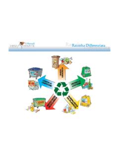
4 Simple 1:1 voltage balun A voltage transformer type balun uses magnetic transfer (transformer action) to produce a balanced signal at the output. The 1:1 impedance transformation is achieved by making the impedance of each winding the same. If changing the number of turns on one (or more) winding changes the Simple 1:1 current balun A 1:1 current balun controls currents. There is NO transformer action. Equal and opposite (balanced) currents cancel each other out and present a low impedance. Common mode currents produce a mutually inductive magnetic field that presents a high impedance to these, unwanted, signals.
5 If the number of turns on one winding The balun and The unun - page 3 voltage, it is a voltage balun . Working currents flow (indicated by the arrows in the above diagram) are induced through the core, in the same sense in the voltage balun but are in an opposite sense cancelling each other out (are not induced through the core) in a current balun . is made different to the other, the action will remain the same except that there will now be a small impedance associated with balanced currents but still a much higher impedance for to common mode currents.
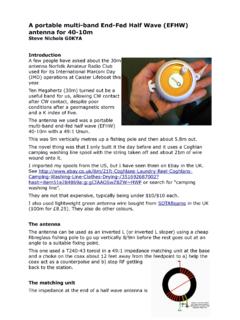
6 If changing the number of turns on one (or more) winding changes the current, it is a current balun . Common Mode currents Coaxial cables with shields more than several skin depths thick always carry equal and opposite flowing currents on the inside of their shields and their centre conductors. Current direction and current ratio between the centre conductor and inside of the shield in a non-radiating coaxial line is no different than currents in each conductor of a perfectly balanced ladder line. In both unbalanced coaxial lines and balanced lines, the two conductors making up the line carry equal and opposite flowing currents.
7 when currents flow without close-by opposing currents, we call the unopposed portion of current common mode current. Common mode currents promote or encourage external coupling and radiation. In a dipole antenna, or any antenna for that matter, common mode currents in the antenna element are responsible for radiation. In the ham shack or along a feed-line, common mode current is responsible for unwanted noise ingress, RFI, RF burns, and a host of other maladies. Common mode currents, in effect, bring the radiating system into the feed-line or station equipment.
8 Common-mode currents, or currents flowing in the same direction, cannot exist inside a coaxial cable at any frequency where the shield is several skin depths thick. Shield skin depth serves to isolate the inside of the shield from the outer wall of the shield. Common mode (same direction) currents can only flow on the outside of the coaxial cable shield. Differential mode currents, or normal transmission line currents, flow on the inner surface of the shield wall. Currents entering and leaving the shield and centre conductor at each end of a coaxial line must be equal and opposite or the cable will radiate.
9 If a coaxial line is not radiating, currents in the shield and centre conductor are exactly balanced and opposite flowing. Both types of transmission lines, balanced and unbalanced, will have equal and opposite currents entering and leaving each conductor when they have minimal radiation. FERRITE vs POWDERED IRON The balun and The unun - page 4 Both ferrite and powdered iron cores are ceramic materials. They consist of small particles of either iron (for powdered iron obviously) or mixtures of iron oxides mixed with binding substances and are fired in a kiln like pottery.
10 Both are more efficient than solid iron. There are advantages and disadvantages to using both. Ferrite saturates (fills up with a magnetic field) at a lower level than powdered iron. After any core saturates, it behaves like just a piece of wire and not like a coil anymore. You must also remember that the relationship between magnetic field strength and ampere turns is not linear so, the closer you are working to the saturation point of any core, the more harmonics (mostly odd harmonics) you produce. Suppose you have a powdered iron core and a ferrite core of the same size.