Transcription of Which piping plan should I choose: API 53A, 53B or 53C?
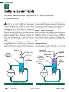
1 PUMPS & SYSTEMS MAY 2010 63 This article is related to an earlier sealing sense that answered the question When and how do I use API Flush plan 53? (June 2005). Now we will focus on the three variances of plan 53 (see Figure 1). Operational FeaturesPlan 53 is the most commonly used auxiliary system for the operation of dual pressurized mechanical seals. It provides a clean external barrier fl uid at a constant or variable pres-sure greater than that of the product pressure on the inner seal to ensure virtually zero emissions to the atmosphere.
2 The mechanical seal will usually contain an internal pumping ring or screw that circulates the barrier fl uid through some type of cooling device, Which is installed in close proximity to the pump. From an operational point of view, the system must maintain pressure above product pressure at all times. It must also maintain the barrier fl uid within a specifi c temperature range such that the seal faces operate under favorable lubricating conditions, typically below 150 deg F for most barrier fl uids.
3 The saying a cool seal is a happy seal is true in most applications and should be considered during the selection and sizing process of a dual mechanical seal support ConsiderationsFrom a maintenance point of view, the system must allow for replenishment of fresh barrier fl uid without interrup-tion of the operational requirements. The amount of clean, fresh barrier fl uid makeup depends on the leak rate of the seal faces. The refi ll frequency can be estimated or predicted by comparing the available volume of the reservoir with the anticipated leakage of the seal over time.
4 Contact a seal OEM for estimated leak rates since they allow the use of barrier fl uid consumption as a benchmark for the performance of the seal and predict the need for maintenance. All three plans require some type of makeup system for barrier fl uid lost through natural leakage of the mechanical seal. The makeup system can be a simple hand pump (see Figure 2) or a more elaborate system that automatically feeds multiple seals. Barrier FluidThe choice of the barrier fl uid is the most important consid-eration for determining the best system.
5 Water-based fl uids will dissipate heat twice as effectively as petroleum-based fl uids and leak rates may be much different for the same operating conditions. The important point is that a water-based fl uid, 100 percent water or glycol/water mixtures, may be used in a smaller system as compared to oil-based fl uids, all other operating conditions being equal. Basis for SelectionPlan 53A is the simplest plan of the three; it has no moving parts and is easy to operate. A gas, usually nitrogen, is used to maintain constant pressure on the barrier fl uid in a stain-less steel reservoir.
6 The gas is typically sourced from a plant system. API 682 specifi es these systems should not be used Which piping plan should I choose : API 53A, 53B or 53C?This month s sealing sense was prepared by FSA Member Eric Vanhie From the voice of the fl uid sealing industry SEALING SENSEF igure 1. Overview of API plan 53A, 53B and 53C64 MAY 2010 PUMPS & SYSTEMSFSA Sealing Senseabove 150 psig because of the danger that gas absorption in the barrier fl uid may affect the lubricating state or regime of the sealing reservoir has typical fl uid storing capacities between 1 and 5 gallons.
7 Cooling is obtained by circulating the barrier fl uid over a cooling coil in the reservoir. Cooling water fl ow rates through the coil will vary between 1 and 3 gpm for the majority of applications. Cooling capacity is typically limited to approximately 6 kW for the larger reservoir sizes. The signal for barrier fl uid refi lling is normally delivered by a level switch in the reservoir or by visual monitoring of a level system is commonly used on single overhung pumps and only one dual seal can be operated with each system.
8 A variety of highly standardized products is readily available for ANSI and API applications from most seal OEMs. In plan 53B, the pressurizing gas does not come into direct contact with the barrier fl uid. Instead of the storage and cooling reservoir in plan 53A, a heat exchanger (air or water-cooled) maintains suitable temperatures for the barrier fl uid. A pre-charged bladder-type accumulator maintains reasonably constant barrier pressure. A bottle of nitrogen is used to pre-charge the accumulator and a hand pump brings the loop to the desired barrier pressure.
9 Since a plant nitrogen system is not required, this plan is suitable for remote installations where no or limited utilities are available. From a pressure range standpoint, plan 53B is typically used for pressures between 150 and 750 psig. The size of the accumulator is critical since suffi cient volume compensa-tion must be available to compensate for the barrier fl uid lost from normal leakage of the mechanical seal. Volume expansion of the barrier fl uid must be included in the selection and sizing process.
10 The refi ll signal is created by a pressure switch that senses barrier pressure decay and notifi es the need for refi ll well before the product pressure is reached. Periodic checking of the accumulator pre-charge is necessary and manual refi lling can be used if the anticipated leak rates are reasonable. The heat exchanger allows for larger heat load dissipation as compared to the coil in plan 53A, so this plan can be used for more severe operating conditions, , API 610 overhung and between bearing pump applications.