Transcription of WHITE PAPER Basics of Dual Fractional-N …
1 Skyworks Solutions, Inc. Phone [781] 376-3000 Fax [781] 376-3100 101463B Skyworks Proprietary and Confidential information Products and Product Information are Subject to Change Without Notice May 17, 2005 1 WHITE PAPER Basics of dual Fractional-N Synthesizers/PLLs The term Fractional-N describes a family of synthesizers that allow the minimum frequency step to be a fraction of the reference frequency. Over the years, a number of methods have been proposed to realize Fractional-N frequency synthesis that are based on the basic concepts of traditional integer-N synthesis [1,5]. Among these methods, three techniques are best known in the industry: fractional divider-based, current injection-based, and modulator-based Fractional-N . This WHITE PAPER describes these methods and provides a general discussion of the use of Fractional-N synthesizers in a low-cost, low-power radio.
2 Basics of Phase Locked Loops (PLLs) A PLL is a negative feedback loop in which the phase of a generated signal is forced to follow that of a reference signal. A basic modern PLL comprises a reference source, a phase frequency detector, a charge pump, a loop filter, and a Voltage Controlled Oscillator (VCO). The output of the VCO is phase-compared with the reference at the Phase Frequency Detector (PFD). The polarity of the measured phase difference is used to turn on the pump-up or pump-down current source in the charge pump. As a result, some charge is transferred to or taken away from the integrating capacitor in the loop filter. The amount of charge is proportional to the magnitude of the phase difference. This, in turn, results in an adjustment in the tuning voltage of the VCO so that its phase is retarded or advanced. The loop is designed so that the phase error is corrected. The function of the PFD also ensures that it switches on the right current source ( , pump-up current or pump-down current) to speed up or slow down the VCO in case of a frequency difference between the two incoming signals to the PFD.
3 When the loop reaches lock condition, the frequency of the generated signal is also equal to that of the reference. Fundamentals of an Integer-N Frequency Synthesizer When a frequency divider is placed between the VCO and the PFD, the PLL becomes a frequency synthesizer where the output is an integer multiple of the reference. A frequency divider is, basically, a state machine clocked by the VCO. A rising edge occurs at the divider output every N number of VCO cycles. Here, N is a predetermined number and is referred to as the division ratio. Because the loop forces the frequency of the divider output to track that of the reference, the VCO is N times as fast as the reference, as illustrated by Equation 1: refVCOf Nf = (1) where: fVCO = output frequency of the VCO fref = the reference frequency Equation 1 indicates that a frequency synthesizer can be viewed as a frequency multiplier with its input and output frequency related.
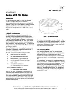
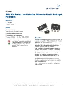
4 If the frequency division ratio is programmable, an integer-N frequency synthesizer is formed as illustrated in Figure 1. A programmable divider is a loadable digital counter. Its output completes a cycle every N VCO cycles, much like a simple frequency divider. frefPhaseDetectorProgrammable NS613 Figure 1. Basic Integer-N Synthesizer Architecture WHITE PAPER Fractional-N SYNTHESIZERS/PLLS Skyworks Solutions, Inc. Phone [781] 376-3000 Fax [781] 376-3100 2 May 17, 2005 Skyworks Proprietary and Confidential information Products and Product Information are Subject to Change Without Notice 101463B VCOO utputDividerOutputS614 Figure 2. Timing Diagram of a Fractional-N Frequency Divider Since the division ratio is programmable, the output frequency (fVCO) can be changed by programming N to a new value. Note that the synthesizable frequencies can only be integer multiples of the input reference frequency (therefore, the name integer-N synthesizer ).
5 As a result, the minimum channel spacing, or frequency step size, is equal to fref. This is a primary constraint of integer-N synthesizers. Fractional-N Frequency Synthesis The frequency synthesized by a Fractional-N synthesizer can be a non-integer multiple of the reference, as illustrated by the following equation: refVCOfMk Nf += where k and M are integers The variable M is a measure of the fractionality that a Fractional-N synthesizer can provide. It is usually referred to as fractional modulus or fractional denominator. The integer number k can assume any number between 0 and M. The non-integer number (N + k/M) is often written as , where the dot denotes a decimal point, and N and F represent the integer and fractional parts of the number, respectively. Traditional Fractional-N synthesis methods are based on the basic concepts of integer N synthesis [1,5]. The three most common methods fractional divider-based, current injection-based, and modulator-based are described below.
6 The last two methods are based on the concept of division ratio averaging. fractional Divider-Based Fractional-N This technique evolves from the fundamental principles of integer-N synthesis. The only difference is that the frequency divider is replaced with a fractional divider. A fractional frequency divider is no longer a simple digital counter. The period of the divider output (Tdo) is given by the following equation: () NT += where: = a fractional number Tvco = the period of the VCO It s important to mention that once N and are set, the period of a fractional divider output is ideally not time varying. In other words, a rising edge occurs at the output each N and VCO cycle. The timing diagram in Figure 2 illustrates the operation of a fractional divider where is equal to As with the case of an integer-N synthesizer, Tdo is forced to follow the reference period. Therefore, () NT += or: () Nf += where Tref is the reference period.
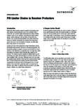
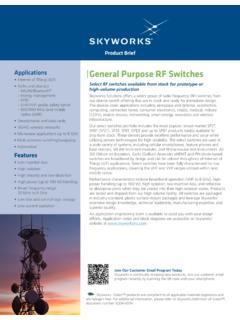
7 A simple fractional frequency divider circuit is shown in Figure 3. This block diagram shows a divider comprised of a dual Modulus Divider (DMD), a Delay Locked Loop (DLL), a Multiplexer (MUX), and a Digital Phase Accumulator (DPA). Note, however, that a fractional divider does not have to be based on a DLL [6]. The DLL shown in Figure 4 consists of a set of cascaded, tunable, delay elements; a phase detector; a charge pump; and a D-type flip-flop. The negative nature of the feedback in the DLL ensures that the total delay through the delay line is one VCO cycle. Since the delay elements are, ideally, identical, a VCO period is broken up into Nd equal packets of phase, where Nd is the number of delay elements in the delay line. A simple DPA is made up of an adder and a register, as illustrated in Figure 4. The register is clocked by the reference. The input to the DPA is an m-bit word. The contents of the register are used to control the MUX.
8 On every reference rising edge, the contents are incremented by the value of the input, x, which is represented by an m bits word. The output of the DPA ( , the carry-out of the adder) is a one-bit quantization of the input. The number of bits in the accumulator (m) is related to the number of discrete packets of phase by the following equation: md2N= WHITE PAPER Fractional-N SYNTHESIZERS/PLLS Skyworks Solutions, Inc. Phone [781] 376-3000 Fax [781] 376-3100 101463B Skyworks Proprietary and Confidential information Products and Product Information are Subject to Change Without Notice May 17, 2005 3 InN/N + 1 DQDelayLineC12 NPDCPC harge PumpPhase DetectorOutputCarry Out(M Bits)Divider ControlMUXDPAS615 Figure 3. Example of Fractional-N Divider Implementation AdderRegistermClockCarry OutInputS616 Figure 4. Design of a Simple Digital Phase Accumulator The output of the DPA controls the DMD.
9 When carry-out is high, the DMD divides by N + 1 as opposed to N when carry-out is low. In the following example, the fractional division ratio, N + , for a DPA input of x, is equal to N + x/2m. Suppose the DPA has three bits and, therefore, the delay line has eight elements. Each phase packet corresponds to 1/8 of a VCO cycle. Also, assume that the input is equal to 2, which corresponds to a of 2/8. When no carry-out occurs, the DMD divides by N. Its output, however, is not immediately presented to the PFD of the PLL. Rather, it is delayed by a number of phase packets controlled or selected by the MUX. This number is equal to the content of the DPA, which is incremented by 2 every reference cycle. This means that the output is phase-shifted by a progressively increasing number of phase packets ( , 0, 2, 4, 6, 8) each reference cycle. As a result, the period of the DMD output is increased by 2/8 of a VCO cycle.
10 Therefore, the effective division ratio becomes N + , which is what it should be. When the DPA content reaches 8, the content of the DPA is reset, and the output of the DMD is not delayed by the delay line. However, this coincides with a carry-out, which forces the DMD to divide by N + 1. This is equivalent to the DMD dividing by N and its output being delayed by 8 phase packets ( , one VCO cycle). The design of the fractional divider dictates the fractional modulus or fractional denominator to be Nd, the number of delay elements. Because all the elements in the delay line operate at the VCO speed, the added power consumption can be significant, especially when the VCO frequency and/or fractionality is high. Another drawback of this method is that the edges of the fractional divider output may be noisy as a result of jitter on the WHITE PAPER Fractional-N SYNTHESIZERS/PLLS Skyworks Solutions, Inc.