Transcription of Wide Input, Isolated Eighth-Brick DC-DC Converters
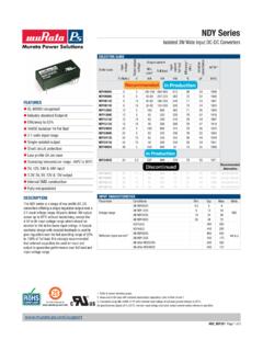
1 UWE-100-120W SeriesWide input , Isolated Eighth-Brick DC-DC Page 1 of full details go Industry-standard through-hole eighth-brickpackage wide input range of 18-75 Vdc or9-36 Vdc (12 Vout only) Fixed outputs from , 5 and 12 Volts DC up to120 Watts Synchronous rectifi cation yields very high ef-fi ciency and low power dissipation Operating temperature range from -40 C to+85 C with derating Up to 2250 Volt DC isolation Outstanding thermal performance and derating Extensive self-protection, over temperature andoverload features On/Off control, trim and remote sense functions Certifi ed to UL/EN/IEC 60950-1, No. 60950-1, 2nd Edition, safety approvals andEN55022/CISPR22 standards Pre-bias operation for startup protectionThe UWE series open frame DC-DC Converters deliver up to 120 Watts in an industry-standard Eighth-Brick through-hole package. This format can plug directly into quarter- brick pin outs. Several standard fi xed-output voltages from Vdc to 12 Vdc assure compatibility in embedded equipment, CPU cards and instrument subsystems.
2 The extended 4-to-1 input voltage range is ideal for battery-powered, telecom or portable applications. Very high effi ciency means no fans or tempera-ture deratings in many applications. An optional baseplate extends operation into most conceivable environments. The synchronous rectifi er design uses the maxi-mum available duty cycle for greatest effi ciency and low power dissipation. These devices deliver low output noise, tight line/load regulation, stable no-load operation and fast load step response. All units are precision assembled in a highly auto-mated facility with ISO-traceable manufacturing quality standards. Isolation of 2250 Volts assures safety and fully differential (fl oating) operation for greatest application fl exibility. On-board Sense terminals compensate for load line voltage errors at high output currents. Outputs are trimmable within 10% of nominal wealth of protection features prevents damage to both the converter and outside circuits.
3 Inputs are protected from under voltage and outputs fea-ture short circuit protection, over current and over temperature shut down. Overloads automatically recover using the hiccup technique upon fault removal. The UWE is certifi ed to standard safety and EMI/RFI approvals. All units meet RoHS-6 hazardous materials OVERVIEWThe UWE Series " Eighth-Brick " DC-DC Converters are high-current Isolated power modules designed for use in high-density system boards. Typical unitsFigure 1. Simplifi ed Block Diagram+SENSE+VOUT VOUT SENSETRIM VIN+VINON/OFFCONTROLSWITCHDRIVET ypical topology is ,TRIM AND FEEDBACKVOLTAGEREGULATORSSISOLATIONPWMT ypical unitsUWE-100-120W SeriesWide input , Isolated Eighth-Brick DC-DC Page 2 of NUMBER STRUCTURENote:Some model number combinations may not be available. See website or contact your local Murata sales representative.*Minimum order quantity is available with standard pin length Configured Part Numbers: 1. UWE-31311-C (special version of the UWE-12/10-Q48NB-C)a.
4 Includes conformal coatingb. Isolation tested to 2,828 Vdc input -to-Output per IEEE 1613c. Pin length of inches ( )SPECIFICATION SUMMARY AND ORDERING GUIDE Root Model OutputInputEfficiencyDimensionsVout (V) Iout (A)Power (W)R/N (mVp-p)Regulation (%)Vin Nom. (V)Range (V)Iin, min load (mA)Iin, full load (A) (Inches)Case (mm) Please refer to the part number structure for additonal ordering model numbers and options. All specifications are typical at nominal line voltage, nominal output voltage and full load, +25 C unless otherwise noted. See detailed specifications. External capacitors used for testing: with appropriate voltage and current ratings, output capacitors are 1 F in parallel with 10 F. input cap is 33 F. All caps are low ESR types. Contact Murata Power Solutions for details. I/O caps are necessary for our test equipment. The values and number of capacitors may be modified depending on the Rated OutputCurrent in AmpsEighth- brick PackageNominal Output VoltageE-/Q48-12 Unipolar, Single-OutputU10 NBInput Voltage RangeQ48 = 18-75 VoltsQ12 = 9-36 Volts (12 Vout only)CRoHS Hazardous Materials ComplianceC=RoHS-6, standard (does not claim EU RoHS exemption 7b lead in solder)- wide input RangeWOn/Off Control Logic Option N = Negative logicP = Positive logicBaseplate (optional) Blank = No baseplate B = Baseplate installedLX Blank = Standard pin length inches ( )L1 = Pin length inches ( )*L2 = Pin length inches ( )*Pin Length OptionHConformal Coating OptionBlank = No coating, standardH = Coating added, optional* (built to order; contact Murata Power Solutions for MOQ and lead times.)
5 This product has been replaced with a new and improved version. Please see the UWE-Q12 Series datasheet for product information. Please click here to view the product datasheet. Please click here to view the Product Change Notification. UWE-100-120W SeriesWide input , Isolated Eighth-Brick DC-DC Page 3 of SPECIFICATIONS, MAXIMUM RATINGSCONDITIONS AND COMMENTS MINIMUMTYPICAL/NOMINALMAXIMUMUNITSI nput Voltage, ContinuousFull power operation80 VdcInput Voltage, TransientOperating or non-operating, 100 mS max. duration100 VdcIsolation VoltageInput to output2250 VdcInput Reverse PolarityNone, install external fuseNoneVdcOn/Off Remote ControlPower on or off, referred to -Vin015 VdcOutput CurrentCurrent-limited, no damage, short-circuit protected030 AStorage Temperature RangeVin = Zero (no power)-55125 CAbsolute maximums are stress ratings. Exposure of devices to greater than any of these conditions may adversely affect long-term reliability. Proper operation under conditions other than those listed in the Performance/Functional Specifications Table is not implied or AND COMMENTS Operating voltage range184875 VdcRecommended External FuseFast blow12 AStart-up threshold, Turn OnRising input shutdown, Turn OffFalling input shutdownNAVdcReverse Polarity ProtectionNone, install external fuseNoneVdcInternal Filter TypePi-typeInput currentFull Load ConditionsVin = LineVin = Short Circuit input Current150200mANo Load input CurrentIout = minimum, unit=ON90125mAStandby Mode input Current (Off, UV, OT)48mAReflected (back) ripple current no filtering500700mA, P-PReflected (back) ripple current Measured at input with specified filter5070mA, P-PPre-biased startupMonotonicGENERAL AND SAFETYE fficiencyVin=24V, full load8990%Vin=min.
6 To , full Voltage, input to outputNo baseplate2250 VdcIsolation Voltage, input to outputWith baseplate2250 VdcIsolation Voltage, input to baseplateWith baseplate1500 VdcIsolation Voltage, output to baseplateWith baseplate750 VdcInsulation Safety RatingbasicIsolation Resistance100M Isolation Capacitance1000pFSafetyCertified to UL-60950-1, , IEC/EN60950-1, 2nd edition (pending)Ye sCalculated MTBFPer Telcordia SR332, issue 1, class 3, ground fixed, Tambient=+40 CTBDH ours x 103 DYNAMIC CHARACTERISTICSF ixed Switching Frequency195215235 KHzStartup TimePower on, Vout regulated2030mSStartup TimeRemote ON to Vout regulated1020mSDynamic Load Response50-75-50% load step, settling time to within 2% of SecDynamic Load Peak Deviationsame as above 500mVFEATURES AND OPTIONSR emote On/Off Control N suffix:Negative Logic, ON stateON = Pin grounded or external voltage01 VNegative Logic, OFF stateOFF = Pin open or external Currentopen collector/drain12mA P suffix:Positive Logic, ON stateON = Pin open or external Logic, OFF stateOFF = Ground pin or external Currentopen collector/drain12mABase Plate"B" suffixUWE-100-120W SeriesWide input , Isolated Eighth-Brick DC-DC Page 4 of Output Output VoltageNo AccuracyAt 50% load-11% of Voltage RangeUser-adjustable (see trim formulas)-1010% of ProtectionVia magnetic Current Range03030 AMinimum LoadNo minimum loadCurrent Limit Inception98% of Vnom.
7 , after warmup333544 AShort CircuitShort Circuit CurrentHiccup technique, autorecovery within 1% of Vout510 AShort Circuit Duration (remove short for recovery)Output shorted to ground, no damageContinuousShort circuit protection methodHiccup current limitingRegulationLine RegulationVin=min. to max., Vout=nom., nom load of VoutLoad RegulationIout=min. to max of VoutRipple and Noise 5 Hz- 20 MHz BW90125mV pk-pkTemperature CoefficientAt all of CMaximum Capacitive Loading Low ESR0470010,000 FMECHANICAL (THROUGH HOLE MODELS)Outline (Please refer to outline drawing) (without baseplate) (with baseplate) Hole Pin DiameterDiameter of pins standard & & Hole Pin MaterialCopper alloyTH Pin Plating Metal and ThicknessNickel subplate50 -inchesGold overplate5 -inchesBaseplate MaterialAluminumENVIRONMENTALO perating Ambient Temperature RangeSee derating-4085 CStorage TemperatureVin = Zero (no power)-55125 COperating Base Plate TempNo derating required-40100 Thermal Protection/ShutdownMeasured at hotspot135140150 CElectromagnetic InterferenceExternal filter is requiredConducted, EN55022/CISPR22 BClassRadiated, EN55022/CISPR22 BClassRoHS ratingRoHS-6 FUNCTIONAL SPECIFICATIONS, (CONT.)
8 Notes Unless otherwise noted, all specifications are at nominal input voltage, nominal output voltage and full conditions are +25 Celsius ambient temperature, near sea level altitude, airflow of 300lfm for extended operation models are tested and specified with external parallel 1 F and 10 F output 33 F external input capacitor with appropriate voltage and current rating is used. All capacitors are low-ESR types wired close to the converter. The values and number of capacitors may be modified depending on the application. input (back) ripple current is tested and specified over 5 Hz to 20 MHz bandwidth. input filtering is Cbus=220 F, Cin=33 F and Lbus=12 H. All models are stable and regulate to specification under no load. The Remote On/Off Control is referred to -Vin. For external transistor control, use open collector logic or equivalent. NOTICE Please use only this customer data sheet as product documentation when laying out your printed circuit boards and applying this product into your application.
9 Do NOT use other materials as official documentation such as advertisements, product announcements, or website strive to have all technical data in this customer data sheet highly accurate and complete. This cus-tomer data sheet is revision-controlled and dated. The latest customer data sheet revision is normally on our website ( ) for products which are fully released to Manufacturing. Please be especially careful using any data sheets labeled Preliminary since data may change without be aware of small details that may affect your application and PC board layouts. Study the Mechanical Outline drawings, input /Output Connection table and all footnotes very carefully. Please contact Murata Power Solutions if you have any questions. If reverse polarity is accidentally applied to the input , to ensure reverse input protection, always connect an external input fuse in series with the +VIN input . Use approximately twice the full input current rating with nominal input SeriesWide input , Isolated Eighth-Brick DC-DC Page 5 of DATA, Current Temperature Derating @ sea level (Vin = 24V, air flow from Pin 3 to Pin 1, no baseplate)Maximum Current Temperature Derating @sea level (Vin = 24V, air flow from Pin 3 to Pin 1, with baseplate)313029282726252423222120191817 16303540455055606570758085 Ambient Temperature ( C)Output Current (Amps) m/s (65 LFM) m/s (100 LFM) m/s (200 LFM) m/s (300 LFM) m/s (400 LFM)Maximum Current Temperature Derating @sea level (Vin = 48V, air flow from Pin 3 to Pin 1, no baseplate)Maximum Current Temperature Derating @sea level (Vin = 48V, air flow from Pin 3 to Pin 1, with baseplate)313029282726252423222120191817 16303540455055606570758085 Ambient Temperature ( C)Output Current (Amps) m/s (65 LFM) m/s (100 LFM) m/s (200 LFM) m/s (300 LFM) m/s (400 LFM)
10 3130292827262524232221201918171630354045 5055606570758085 Ambient Temperature ( C)Output Current (Amps) m/s (65 LFM) m/s (100 LFM) m/s (200 LFM) m/s (300 LFM) m/s (400 LFM)Efficiency vs. Line Voltage and Load Current @ 25 CPower Dissipation vs. Line and Load555963677175798387919512345678910 Vin = 24 VVin = 36 VVin = 18 VVin = 48 VVin = 60 VVin = 75 VLoad Current (Amps) Efficiency (%)13579111326101248141618202224262830 Vin = 24 VVin = 36 VVin = 18 VVin = 48 VVin = 60 VVin = 75 VLoad Current (Amps) Dissipation (Watts)313029282726252423222120191817163 03540455055606570758085 Ambient Temperature ( C)Output Current (Amps) m/s (65 LFM) m/s (100 LFM) m/s (200 LFM) m/s (300 LFM) m/s (400 LFM)UWE-100-120W SeriesWide input , Isolated Eighth-Brick DC-DC Page 6 of DATA, Delay (Vin=48V, Iout=30A, Cout=10000 F, Ta=+25 C) Trace1=Vin, Trace2= Enable Delay (Vin=48V, Iout=0A, Cout=0, Ta=+25 C) Trace1=Enable, race2= Enable Delay (Vin=48V, Iout=30A, Cout=0, Ta=+25 C) Trace1=Enable, Trace2= Enable Delay (Vin=48V, Iout=30A, Cout=10000 F, Ta=+25 C)Startup Delay (Vin=48V, Iout=0A, Cout=0, Ta=+25 C) Trace1=Vin, Trace2= Delay (Vin=48V, Iout=30A, Cout=0, Ta=+25 C)