Transcription of Wide Input Range, Synchronizable, PWM SLIC Power Supply
1 General DescriptionThe MAX1856 offers a low-cost solution for generating aSLIC (ringer and off-hook) Power Supply . Using standardoff-the-shelf transformers from multiple vendors, theMAX1856 generates various output voltages: -24V and-72V (dual output) for both ringer and off-hook supplies forvoice-enabled broadband consumer premises equipment(CPE), -48V for IP phones and routers, -5V and -15V (sin-gle or dual output) for DSL CO line drivers, or negativevoltages as high as -185V for MEMS bias supplies. Theoutput voltages are adjusted with an external to its wide operating voltage range, the MAX1856operates from a low-cost, unregulated DC Power supplyfor cost-sensitive applications like xDSL, cable modems,set-top boxes, LMDS, MMDS, WLL, and FTTH CPE.
2 TheMAX1856 provides low audio-band noise for talk batteryand a sturdy output capable of handling the ring trip con-ditions for ring operating frequency can be set between 100kHz and500kHz with an external resistor in free-running mode. Fornoise-sensitive applications, the MAX1856 s operating fre-quency can be synchronized to an external clock over itsoperating frequency flyback topology allows operation close to 50% dutycycle, offering high transformer utilization, low ripple cur-rent, and less stress on Input and output soft-start minimizes startup stress on the inputcapacitor, without any external MAX1856 s current-mode control scheme does notrequire external loop compensation.
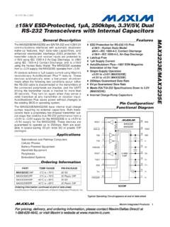
3 The low-side current-sense resistor provides accurate current-mode controland overcurrent Ringer and Off-Hook voltage GeneratorsCable and DSL ModemsSet-Top BoxesWireless Local LoopFTTHLMDS/MMDSR outersIndustrial Power SuppliesCO DSL Line Driver SuppliesMEMS Bias SuppliesFeatures Low-Cost, Off-the-Shelf Transformer 3V to 28V Input Range Low Audio-Band Noise on Talk Battery Effectively Handles Ring Trip Transients Powers 2-, 4-, or 12-Line Equipment High Efficiency Extends Battery Life During Life-Line Support Conditions Adjustable 100kHz to 500kHz SwitchingFrequency Clock Synchronization Internal Soft-Start Current-Mode PWM and Idle Mode ControlScheme Logic-Level Shutdown 10-Pin MAX PackageMAX1856 wide Input Range, Synchronizable, PWM SLIC Power Supply_____Maxim Integrated Products1 CSEXT1222 FBLDOFREQINPUT3V TO 28 VGNDREFVCCPGNDSYNC/SHDNMAX1856 OUT2-72 VOUT1-24 VTypical Operating CircuitOrdering Information19-1898; Rev 0.
4 2/01 For price, delivery, and to place orders, please contact Maxim Distribution at 1-888-629-4642,or visit Maxim s website at RANGEPIN-PACKAGEMAX1856 EUB-40 C to +85 C 10 MAXIdle Mode is a trademark of Maxim Integrated Input Range, Synchronizable, PWM SLIC Power Supply2_____ABSOLUTE MAXIMUM RATINGSELECTRICAL CHARACTERISTICS(VCC= SYNC/SHDN,VCC = 5V, VLDO = 5V, ROSC= 200k , TA= 0 C to +85 C. Typical values are at TA= +25 C, unless otherwise noted.)Stresses beyond those listed under Absolute Maximum Ratings may cause permanent damage to the device. These are stress ratings only, and functionaloperation of the device at these or any other conditions beyond those indicated in the operational sections of the specifications is not implied.
5 Exposure toabsolute maximum rating conditions for extended periods may affect device , SYNC/SHDNto GND .. to +30 VPGND to GND .. to + , FREQ, FB, CS to to +6 VEXT, REF to to (VLDO+ )LDO Output to +20mALDO Short Circuit to GND ..<100msREF Short Circuit to GND ..ContinuousContinuous Power Dissipation (TA= +70 C)10-Pin MAX (derate C above +70 C) ..444mWOperating Temperature Range ..-40 C to +85 CJunction Temperature ..+150 CStorage Temperature Range ..-65 C to +150 CLead Temperature (soldering, 10s) ..+300 CPARAMETERSYMBOLCONDITIONSMINTYPMAXUNITS PWM CONTROLLER328 VOperating Input voltage RangeVCCVCC = Input CurrentIFBVFB = RegulationVCS = 0 to 100mV for 0 to ILOAD(MAX) RegulationTypically per % duty factor on ThresholdVCS85100115mVCS Input CurrentICSCS = GND1 AIdle Mode Current-SenseThreshold51525mVVCC Supply Current (Note 1)ICCVFB = , VCC = 3V to 28V250400 AShutdown Supply CurrentSYNC/SHDN = GND, VCC = AREFERENCE AND LDO REGULATOR5V VCC Output VoltageVLDORLDO = 400 3V VCC LockoutThresholdVUVLOVLDO falling edge, 1% hysteresis (typ) to FB voltage (Note 2)
6 VREFRREF = 10k , CREF = Load RegulationIREF = 0 to 400 A-2-10mVREF Undervoltage LockoutThresholdRising edge, 1% hysteresis (typ) = 100k 1%425500575 ROSC = 200k 1%225250275 Oscillator FrequencyfOSCROSC = 500k 1%85100115kHzROSC = 100k 1%869094 ROSC = 200k 1%879093 Maximum Duty CycleDROSC = 500k 1%869094%MAX1856 wide Input Range, Synchronizable, PWM SLIC Power Supply_____ 3 ELECTRICAL CHARACTERISTICS (continued)(VCC= SYNC/SHDN,VCC = 5V, VLDO = 5V, ROSC= 200k , TA= 0 C to +85 C. Typical values are at TA= +25 C, unless otherwise noted.)PARAMETERSYMBOLCONDITIONSMINTYPMA XUNITSM inimum EXT Pulse Width290nsMinimum SYNC Input SignalDuty Cycle2045%Minimum SYNC InputLow Pulse Width50200nsMaximum SYNC InputRise/Fall Time200nsSYNC Input Frequency RangefSYNC100500kHzSYNC/SHDN Falling Edge toShutdown DelaytSHDN50 sSYNC/SHDN Input High Input Low = Input CurrentVSYNC/SHDN = AEXT Sink/Source CurrentIEXTEXT forced to 2V1 AEXT On-ResistanceRON(EXT)EXT high or low25 ELECTRICAL CHARACTERISTICS(VCC= SYNC/SHDN,VCC = 5V, VLDO = 5V, ROSC= 200k , TA= -40 C to +85 C, unless otherwise noted.)
7 (Note 3)PARAMETERSYMBOLCONDITIONSMINTYPMAXUNIT SPWM CONTROLLER328 VOperating Input voltage RangeVCCVCC = Input CurrentIFBVFB = ThresholdVCS85115mVCS Input CurrentICSCS = GND1 AVCC Supply Current (Note 1)ICCVFB = , VCC = 3V to 28V400 AShutdown Supply CurrentSYNC/SHDN = GND, VCC = 28V6 AREFERENCE AND LDO REGULATOR5V VCC Output VoltageVLDORLDO = 400 3V VCC to FB voltage (Note 2)VREFRREF = 10k , CREF = Load RegulationIREF = 0 to 400 A-10mVREF Undervoltage LockoutThresholdRising edge, 1% hysteresis (typ) = 100k 1%425575 ROSC = 200k 1%222278 Oscillator FrequencyfOSCROSC = 500k 1%85115kHzMAX1856 wide Input Range, Synchronizable, PWM SLIC Power Supply4_____PARAMETERSYMBOLCONDITIONSMIN TYPMAXUNITSROSC = 100k 1%8694 ROSC = 200k 1%8793 Maximum Duty CycleDROSC = 500k 1%8694%Minimum SYNC Input SignalDuty Cycle45%Minimum SYNC InputLow Pulse Width200nsSYNC Input Frequency RangefSYNC100500kHzSYNC/SHDN Input High Input Low = Input CurrentVSYNC/SHDN = 28V10 AEXT On-ResistanceRON(EXT)EXT high or low5 ELECTRICAL CHARACTERISTICS (continued)
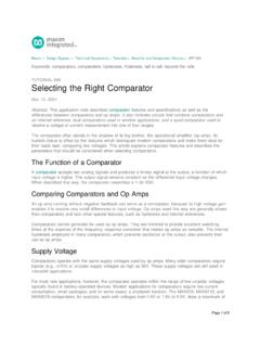
8 (VCC= SYNC/SHDN,VCC = 5V, VLDO = 5V, ROSC= 200k , TA= -40 C to +85 C, unless otherwise noted.) (Note 3)Note 1:This is the VCCcurrent consumed when active, but not switching, so the gate-drive current is not 2:The reference output voltage (VREF) is measured with respect to FB. The difference between REF and FB is guaranteed tobe within these limits to ensure output voltage 3:Specifications to -40 C are guaranteed by design, not production Operating Characteristics(Circuit of Figure 1, VCC= VSYNC/SHDN= 12V, VOUT1= -24V, VOUT2= -72V, ROSC= 200k , unless otherwise noted.) OUTPUT VOLTAGEvs. LOAD CURRENTMAX1856 toc01 IOUT1 (mA)VOUT1 (V)VIN = 5 VVIN = 12 VVIN = 24 VVOUT1 = -24 VVOUT2 = -72 VIOUT2 = CROSS-REGULATION VOLTAGEvs.
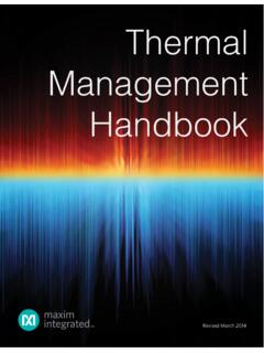
9 LOAD CURRENTMAX1856 toc02 IOUT1 (mA)VOUT2 (V)VIN = 5 VVIN = 24 VVOUT1 = -24 VVOUT2 = -72 VIOUT2 = 5mAVIN = 12V50607090801000100200300400500600700 EFFICIENCY vs. LOAD CURRENT(-24V OUTPUT)MAX1856 toc03 IOUT1 (mA)EFFICIENCY (%)VOUT1 = -24 VVOUT2 = -72 VIOUT2 = 5mAVIN = 5 VVIN = 24 VVIN = 12 VMAX1856 wide Input Range, Synchronizable, PWM SLIC Power OUTPUT VOLTAGEvs. Input VOLTAGEMAX1856 toc07 VIN (V)VOUT1 (V)VOUT1 = -24 VIOUT1 = 100mAVOUT2 = -72 VIOUT2 = 100mAVOUT1 = -24 VIOUT1 = 50mAVOUT2 = -72 VIOUT2 = OUTPUT VOLTAGEvs. Input VOLTAGEMAX1856 toc08 VIN (V)VOUT1 (V)VOUT1 = -24 VIOUT1 = 100mAVOUT2 = -72 VIOUT2 = 100mAVOUT1 = -24 VIOUT1 = 50mAVOUT2 = -72 VIOUT2 = 50mA50607080901000105152025 DUAL-OUTPUT EFFICIENCYvs.
10 Input VOLTAGEMAX1856 toc09 VIN (V)EFFICIENCY (%)VOUT1 = -24 VIOUT1 = 100mAVOUT2 = -72 VIOUT2 = 100mAVOUT1 = -24 VIOUT1 = 50mAVOUT2 = -72 VIOUT2 = OUTPUT VOLTAGEvs. LOAD CURRENTMAX1856 toc10 IOUT2 (mA)VOUT2 (V)VOUT = -48 VFIGURE 4 VIN = 5 VVIN = 24 VVIN = 12V50607080901000100200300400 EFFICIENCY vs. LOAD CURRENT(-48V OUTPUT)MAX1856 toc11 IOUT2 (mA)EFFICIENCY (%)VOUT = -48 VFIGURE 4 VIN = 5 VVIN = 24 VVIN = 12V050150100200250010515202530 Supply CURRENTvs. Input VOLTAGEMAX1856 toc12 Input voltage (V) Supply CURRENT ( A)CURRENT INTO VCC PINROSC = 500k Typical Operating Characteristics (continued)(Circuit of Figure 1, VCC= VSYNC/SHDN= 12V, VOUT1= -24V, VOUT2= -72V, ROSC= 200k , unless otherwise noted.)