Transcription of Wiring Code Identification Information
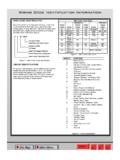
1 Main MenuSite MapALLIN+OUT-PRINTW iring code Identification InformationWIRE code Identification Each wire shown in the diagrams contains a code (Fig. 1) which identifies the main circuit, part of the main circuit, gauge of wire, and color. The color is shown as a two-letter code , which can be identified by referring to the Wire Color code Chart (Fig. 2). Figure 1 Wire Color code Identification CIRCUIT Identification All circuits in the diagrams use an alphanumeric code to identify the wire and its function (Fig. 3). To identify which circuit code applies to a system; refer to the Circuit Identification code Chart. This chart shows the main circuits only and does not show the secondary codes that may apply to some models. Figure 2 Wire Color code Chart Figure 3 Circuit Identification COLOR OF WIRE(Light Blue with Yellow Tracer)GAUGE OF WIRE(18 Gauge)PART OF MAIN CIRCUIT(Varies Depending on Equipment)MAIN CIRCUIT IDENTIFICATIONALB/YL218 ColorCodeColorStandardTracerColorColorCo deColorStandardTracerColorBLBLUEWTORORAN GEBKBKBLACKWTPKPINKBK or WTBRBROWNWTRDREDWTDBDARKBLUEWTTNTANWTDGD ARKGREENWTVTVIOLETWTGYGRAYBKWTWHITEBKLBL IGHTBLUEBKYLYELLOWBKLGLIGHTGREENBK*Wire Color code ChartWITH TRACERCIRCUITFUNCTIONA- Battery FeedB- Brake ControlsC- Climate Controls, EBL, Heated Mirror, Windshield and SeatD- Diagnostic Circuits, Communications, AntennasE- Dimming Illumination CircuitsF- Switched Ignition FeedsG- Gauges, Displays, Monitoring, Body Sensors, Resistive Mux'd SwitchesH-OpenI-Not UsedJ-OpenK- Power Train Control ModuleL- Exterior Lighting, Headlamp LevelingM- Interior and Courtesy LightingN- Fuel Pump, Radiator FanO-Not UsedP- Power Option, Seats, Recliner, Lumbar, Mirrors, Door LocksQ- Power Options, Windows, Vents, Sunroof, Tops, Trunk, Liftgate.
2 Sliding DoorsR-Restraint SystemsS- Suspension/SteeringT- Starter, Transmission, Transaxle, Transfer CaseU-OpenV- Speed ControlW- Washer, WiperX- Sound Systems, HornY-OpenZ- GroundsWiring code Identification InformationMain MenuSite MapALLIN+OUT-PRINTCONNECTORS Connectors shown in the diagrams are identified using the international standard arrows for male and female terminals (Fig. 4). A connector identifier is placed next to the arrows to indicate the connector number (Fig. 4). For viewing connector pin outs, with two terminals or greater, refer to section 8W-80. This section identifies the connector by number and provides terminal numbering, circuit Identification , wire colors and functions. All connectors are viewed from the terminal end unless otherwise specified. To find the connector location in the vehicle, refer to section 8W-90. This section uses the connector Identification number from the Wiring diagrams to provide a figure number reference.
3 TAKE OUTS The abbreviation T/O is used in the component location section to indicate a point in which the Wiring harness branches out to a component. ELECTROSTATIC DISCHARGE (ESD) SENSITIVE DEVICES All ESD sensitive components are solid state and a symbol (Fig. 5) is used to indicate this. When handling any component with this symbol, comply with the following procedures to reduce the possibility of electrostatic charge buildup on the body and inadvertent discharge into the component. If it is not known whether the part is ESD sensitive, assume that it is. 1) Always touch a known ground before handling the part. This should be repeated while handling the part and more frequently after sliding across a seat, sitting down from a standing position or walking a distance. 2) Avoid touching electrical terminals of the part, unless instructed to do so by a written diagnostic procedure. 3) When using a voltmeter, be sure to connect the ground lead first.
4 4) Do not remove the part from its protective packing until it is time to install the part. 5) Before removing the part from its package, ground the package to a known good ground on the vehicle. Figure 4 Electrostatic Discharge Symbol Figure 5 Electrostatic Discharge Symbol Wiring code Identification InformationMain MenuSite MapALLIN+OUT-PRINTWIRING GUIDELINES FOR 2006 DODGE TRUCK AFTERMARKET/BODY BUILDERS 1. Introduction These guidelines are intended as an aid in Wiring design. It is not an all-inclusive list or a substitute for common sense. It is to be used as a supplement to existing good design practices and standards. Additional Information is in the Referenced Publications section. Performing a Failure Mode and Effects Analysis (FMEA) on each completed Wiring design is a good practice to confirm the integrity of the design. This document will be revised periodically, based on advances in technology and operating practices.
5 2. Electrical System A. Modification to the existing vehicle Wiring should be done only with extreme caution. The effects on the completed vehicle electrical system must be considered. Any additional circuitry should be evaluated to ensure that adequate circuit protection provisions will be in place and that feedback loops will not be created. B. The following affects the selection of wire gauge for a particular application: Wire size selection is affected by circuit protection requirements, power distribution requirements and mechanical handling requirements Wire size selection is affected by long-range heat aging characteristics resulting from current loading C. Circuit Protection When adding loads to a base vehicle s protected circuit; be sure that the total electrical load through the base vehicle fuse or circuit breaker is less than the derated device rating. The total electrical load is the sum of the base vehicle circuit current requirement added to the add-on component(s) current requirements.
6 Confirm the load with an ammeter. DO NOT increase the rating of a factory-installed fuse or circuit Any added circuitry must be protected by either the base vehicle fuse or circuit breaker or by a similar device installed by the body builder. In-line fuses should be readily accessible All battery circuits, except the starter motor, must have circuit protection Protections devices for high current loads such as a winch or snowplow motor must be connected directly to the vehicle battery and not to the vehicle power distribution center or other downstream components. Circuit protection devices are designed to protect the Wiring . They may not necessarily protect other components in the event of a short circuit. 3. Harness Routing A. Connectors should be readily accessible, where feasible, to permit ease of installation and serviceability. Accessibility to connectors is good design practice. Examples include fuse blocks, relays, modules, electrical components, junction blocks and ground blocks.
7 B. Provide sufficient wire lengths to permit wire harness serviceability. However, excess lengths should be kept to a minimum to prevent: trapping and pinching during assembly; poor fit and finish; and buzzes, squeaks and rattles. C. Circuits attached to parts or structures that have dynamic (moving) properties must consider adequate slack and strain relief to prevent damage. A few examples are the engine block, door and liftgate harness, shocks, struts and tilt steering columns. Endurance testing must be performed to ensure that designs meet life test criteria. D. Wiring assemblies must not be within one inch (25 mm) of any hot surface or moving mechanism. Movement due to engine rocking will require a greater distance than one inch. Engineering discretion must be used to determine if heat-protection materials are needed to protect the Wiring assembly. The use of abrasion-protection materials (convoluted tubing, fiberglass loom, asphalt loom, friction tape, etc.)
8 Can be used as an added measure in the protection of the harness, but should not be relied upon alone to prevent damage to the Wiring assembly. Some examples of hot surfaces and moving mechanisms are: Plumbing Exhaust manifold Pulleys Oil and fuel lines Catalytic converter Accelerator, brake and clutch pedals Parking brake Mechanisms Auxiliary oil cooler line Floor pan Seat track and recliner mechanisms Choke housing and crossover Window, door and door lock mechanisms Hinges Belts Wire routings should be away from areas where temperatures exceed 180 F and should have a minimum of six inches (152 mm) clearance from exhaust system components. If this is not possible, use heat shields and high-temperature insulation to maintain safe operating temperatures for the Wiring .
9 E. If the harness routes over a sharp edge, sheet metal or plastic, the harness must be protected by one or more of the following: Wiring code Identification InformationMain MenuSite MapALLIN+OUT-PRINT Hole liner Rolled sheet metal edge Convolute, scroll, loom or braided sleeving Edge protector (pinch welt) Wiring clip A. Route wires on the surface of sheet metal to avoid fishing operations and to avoid sharp edges. B. Where Wiring congestion or the possibility of pinching wires exists, the harness design should be a rigid shape and form. This will aid installation and facilitate fit and finish objectives. A good alternative design technique is the use of a stamped sheet metal or a molded plastic trough. C. Eliminate buzzes, squeaks and rattles (BSR) by the use of: Cloth tape Direct connections to devices Locating and/or clipping all connectors whether used or unused Locating and/or clipping wire harnesses Foam wrap, foam tubes, foam doughnuts on clips D.
10 Route Wiring away from areas where fasteners are driven. E. When a wire assembly is routed from the inside to the outside of the vehicle, the transition point must be sealed by: A rubber grommet A rubber tube and grommet (highly recommended for doors and liftgates) A sealed bulkhead-type connection F. Wires on the outside of the vehicle or in a wet environment should: Be routed lower than sealing devices to avoid water intrusion through the wire harness Have a drip loop in the Wiring harness to prevent water intrusion into the connector(s) G. High current circuits and pulse width modulation circuits should not be routed near the radio and other sensitive electronic devices. If rerouting is unavoidable grounded shielding or some other means of isolation may be required. If possible, high current circuits should be routed at least six inches away from the radio. H. Wire harnesses should not be routed closer than one inch (25 mm) from high voltage devices such as the distributor coil or spark plug wires.