Transcription of WIRING DIAGRAM INFORMATION - Ram Body Builder
1 DR_____WIRING DIAGRAM INFORMATION8W01 - 1 WIRING DIAGRAM INFORMATIONTABLE OF CONTENTS pageWIRING DIAGRAM INFORMATIONDESCRIPTIONDESCRIPTION - HOW TO USE WIRING - CIRCUIT INFORMATION ..6 DESCRIPTION - CIRCUIT FUNCTIONS..6 DESCRIPTION - SECTION IDENTIFICATION - CONNECTOR, GROUND ANDSPLICE ..8 DIAGNOSIS AND TESTINGDIAGNOSIS AND TESTING - WIRING PROCEDURESTANDARD PROCEDURE - ELECTROSTATICDISCHARGE (ESD) SENSITIVE DEVICES ..10 STANDARD PROCEDURE - TESTING OF PROCEDURE - TESTING PROCEDURE - TESTING FOR ASHORT TO PROCEDURE - TESTING FOR ASHORT TO GROUND ON FUSES POWERINGSEVERAL PROCEDURE - TESTING FOR AVOLTAGEDROP.
2 12 SPECIAL .. PROCEDURESTANDARD PROCEDURE - WIRE DIAGRAM INFORMATIONDESCRIPTIONDESCRIPTION - HOW TO USE WIRING DIAGRAMSC hrysler LLC LLC vehicles,itis important to understand all of their features and are arranged such that the power (B+) side of the circuit is placed near the top of the page, and the ground(B-) side of the circuit is placed near the bottom of the switches, components, and modules are shown in the at rest position with the doors closed and the key removedfrom the are shown two ways. A solid line around a component indicates that the component is dashed line around the component indicates that the component is being shown is not complete.
3 Incompletecomponents have a reference number to indicate the page where the component is shown is important to realize that no attempt is made on the diagrams to represent components and WIRING as they appearon the vehicle. For example, a short piece of wire is treated the same as a long one. In addition, switches and othercomponents are shown as simply as possible, with regard to function - 2 WIRING DIAGRAM INFORMATION_____DRDR_____WIRING DIAGRAM INFORMATION8W01 - 38W01 - 4 WIRING DIAGRAM INFORMATION_____DRSYMBOLSI nternational symbols are used throughout the WIRING diagrams . These symbols are consistent with those being usedaround the DIAGRAM INFORMATION8W01 - 58W01 - 6 WIRING DIAGRAM INFORMATION_____DRTERMINOLOGYThis is a list of terms and definitions used in the WIRING .
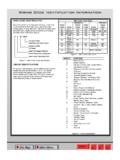
4 Left Hand Drive VehiclesRHD ..Right Hand Drive Transmissions-Front Wheel DriveMTX .. manual Transmissions-Front Wheel DriveAT ..Automatic Transmissions-Rear Wheel DriveMT .. manual Transmissions-Rear Wheel Over Head Cam Over Head Cam Built For Sale In Markets Other Than North AmericaExcept Export .. Vehicles Built For Sale In North AmericaDESCRIPTION - CIRCUIT INFORMATIONEach wire shown in the diagrams contains a code which identifies the main circuit, a specific part of the main circuit,gage of wire, and color. An example would beA 2 18 LB/YL. This is a Battery Feed circuit, level two, eighteengauge, light blue with a yellow COLOR CODE CHARTCOLOR CODECOLORBLBLUEBKBLACKBRBROWNDBDARK BLUEDGDARK GREENGYGRAYLBLIGHT BLUELGLIGHT GREENORORANGEPKPINKRDREDTNTA NVTVIOLETWTWHITEYLYELLOW*WITH TRACERDESCRIPTION - CIRCUIT FUNCTIONSAll circuits in the diagrams use an alpha/numeric code to identify the wire and it s function.
5 To identify which circuit codeapplies to a system, refer to the Circuit Identification Code Chart. This chart shows the main circuits only and does notshow the secondary codes that may apply to some IDENTIFICATION CODE CHARTCIRCUITFUNCTIONABATTERY FEEDDR_____WIRING DIAGRAM INFORMATION8W01 - 7 BBRAKE CONTROLSCCLIMATE CONTROLSDDIAGNOSTIC CIRCUITSEDIMMING ILLUMINATION CIRCUITSFFUSED CIRCUITSGMONITORING CIRCUITS (GAUGES)HMULTIPLEINOT USEDJOPENKPOWERTRAIN CONTROL MODULELEXTERIOR LIGHTINGMINTERIOR LIGHTINGNMULTIPLEONOT USEDPPOWER OPTION (BATTERY FEED)QPOWER OPTIONS (IGNITION FEED)RPASSIVE RESTRAINTSSUSPENSION/STEERINGTTRANSMISSI ON/TRANSAXLE/TRANSFER CASEUOPENVSPEED CONTROL, WIPER/WASHERWWIPERSXAUDIO SYSTEMSYTEMPORARYZGROUNDSDESCRIPTION - SECTION IDENTIFICATION AND INFORMATIONThe WIRING diagrams are grouped into individual sections.
6 If a component is most likely found in a particular group, itwill be shown complete (all wires, connectors, and pins) within that group. For example, the Auto Shutdown Relayis most likely to be found in Group 30, so it is shown there complete. It can, however, be shown partially in anothergroup if it contains some associated diagrams in Section 8W-70 show the entire splice and provide references to other sections the splices 8W-70 only contains splice diagrams that are not shown in their entirety somewhere else in the WIRING 8W-80 shows each connector and the circuits involved with that connector.
7 The connectors are identified usingthe name/number on the DIAGRAM - CONNECTOR, GROUND AND SPLICE INFORMATIONCAUTION: Not all connectors are serviced. Some connectors are serviced only with a harness. A typical exam-ple might be the Supplemental Restraint System connectors. Always check parts availability before attemptinga connectors are identified by a number, as follows:8W01 - 8 WIRING DIAGRAM INFORMATION_____DR In-line connectors located in the engine compartment are C100 series numbers. In-line connectors located in the instrument panel area are C200 series numbers. In-line connectors located in the body are C300 series numbers.
8 Jumper harness connectors are C400 series numbers. Grounds and ground connectors are identified with a G and follow the same series numbering as the in-line con-nectors. Splices are identified with an S and follow the same series numbering as the in-line connectors. In addition,S001 S099 numbers are located in the engine compartment. Component connectors are identified by the component name instead of a number. Multiple connectors on a com-ponent use a C1, C2, etc. 8W-91 contains connector/ground/splice location illustrations. The illustrations contain the connector name(or number)/ground number/splice number and component identification.
9 Connector/ground/splice location charts insection 8W-91 reference the figure numbers of the abbreviation T/O is used in the component location section to indicate a point in which the WIRING harness branchesout to a component. The abbreviation N/S means Not Shown in the illustrationsWARNINGS - GENERALWARNINGS provide INFORMATION to prevent personal injury and vehicle damage. Below is a list of general warnings thatshould be followed any time a vehicle is being : Always wear safety glasses for eye : Use safety stands anytime a procedure requires being under a : Be sure that the ignition switch always is in the off position, unless the procedure requires it to : Set the parking brake when working on any vehicle.
10 An automatic transmission should be in manual transmission should be in : Operate the engine only in a well-ventilated : Keep away from moving parts when the engine is running, especially the fan and : To prevent serious burns, avoid contact with hot parts such as the radiator, exhaust manifold(s), tailpipe, catalytic converter and : Do not allow flame or sparks near the battery. Gases are always present in and around the : Always remove rings, watches, loose hanging jewelry and avoid loose AND TESTINGDIAGNOSIS AND TESTING - WIRING HARNESSTROUBLESHOOTING TOOLSWhen diagnosing a problem in an electrical circuit there are several common tools necessary.