Example: dental hygienist

WIRING DIAGRAMS - Hot Water from A. O. Smith

WIRING DIAGRAMSAPPLICATION TYPE DIAGRAMSEE INSTALLATION MANUALFOR COMPLETE INSTRUCTIONS315268-000 MULTIPLE HEATER PIPINGALL TOP CONNECTING MODELSINSTALL THERMALEXPANSION TANK ON COLDWATER SUPPLY LINE, IFCHECK VALVE ORPRESSURE REDUCINGVALVE IS USED IN SUPPLY. Installation must conform to applicable code and all requirements listed in the installation manual. Each temperature and pressure relief valve (T&P valve) must have a properly-sized discharge pipe installed. See code/installation manual. Each discharge pipe must terminate a maximum of six inches above a floor drain or external to the building. Do not cap or plug the T&P discharge pipes. Suitable metal drain pans should be installed under each Water heater. The pan must be piped to an adequate drain and limit the Water level to a maximum depth of 1-3/4 ( cm) and be two inches (5 cm) wider than the HEATERSELECTRIC HEATERS* PIPE TO ADEQUATE DRAIN ** OPTIONAL FOR HEATER ISOLATIONINSTALL DISCHARGE PIPESWATER HEATERTEMPERATURE AND PRESSURE RELIEF VALVEDISCHARGE PIPE(DO NOT CAP OR PLUG)6 INCH (15 cm) MAXIMUM AIR GAPRETURN LINE(IF USED)CHECK VALVECOLD Water SUPPLY** BALL VALVEOUTLET ATSTORED TEMP.

wiring diagrams application type diagram see installation manual for complete instructions 315268-000 multiple heater piping all top connecting models

Tags:

  Water, Wiring, Smith, Diagrams, Wiring diagram, Wiring diagrams hot water

Information

Domain:

Source:

Link to this page:

Please notify us if you found a problem with this document:

Other abuse

Transcription of WIRING DIAGRAMS - Hot Water from A. O. Smith

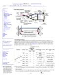
1 WIRING DIAGRAMSAPPLICATION TYPE DIAGRAMSEE INSTALLATION MANUALFOR COMPLETE INSTRUCTIONS315268-000 MULTIPLE HEATER PIPINGALL TOP CONNECTING MODELSINSTALL THERMALEXPANSION TANK ON COLDWATER SUPPLY LINE, IFCHECK VALVE ORPRESSURE REDUCINGVALVE IS USED IN SUPPLY. Installation must conform to applicable code and all requirements listed in the installation manual. Each temperature and pressure relief valve (T&P valve) must have a properly-sized discharge pipe installed. See code/installation manual. Each discharge pipe must terminate a maximum of six inches above a floor drain or external to the building. Do not cap or plug the T&P discharge pipes. Suitable metal drain pans should be installed under each Water heater. The pan must be piped to an adequate drain and limit the Water level to a maximum depth of 1-3/4 ( cm) and be two inches (5 cm) wider than the HEATERSELECTRIC HEATERS* PIPE TO ADEQUATE DRAIN ** OPTIONAL FOR HEATER ISOLATIONINSTALL DISCHARGE PIPESWATER HEATERTEMPERATURE AND PRESSURE RELIEF VALVEDISCHARGE PIPE(DO NOT CAP OR PLUG)6 INCH (15 cm) MAXIMUM AIR GAPRETURN LINE(IF USED)CHECK VALVECOLD Water SUPPLY** BALL VALVEOUTLET ATSTORED TEMP.

2 ** BALL VALVE** BALL VALVE*TEMPERATURE AND PRESSURE RELIEFVALVEMETALDRAINPANRETURN LINE(IF USED)CHECK VALVECOLD Water SUPPLYOUTLET ATSTORED TEMP.** BALL VALVE** BALL VALVE** BALL VALVE*TEMPERATURE AND PRESSURE RELIEFVALVEMETALDRAINPAN


Related search queries