Transcription of WIRING DIAGRAMS - STANDARD MOTORS - …
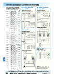
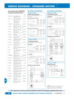
1 Inst Maint & 5/03/2008 10:02 AM Page 6. WIRING DIAGRAMS - STANDARD MOTORS . These DIAGRAMS apply to STANDARD 3 WIRING DIAGRAMS 3 WIRING DIAGRAMS . FRAME INDUCTION MOTORS which are used in the following products:- Diagram DD1 Diagram DD3. Pgs SINGLE SPEED MOTORS TWO-SPEED MOTORS . refer to the name plate data for correct in Dahlander connection (tapped winding). O. Alpha/Beta Series D-4/6. connection High speed Diags. DD 4, 5, 6, 9 L1 L2 L3 E. For delta (D) wired MOTORS Red O. Alpha Series Supply D-34/35 Leads U1 V1 W1. L1 L2 L3 E. Diags. DD 4, 5, 6, 9. W2 U2 V2 Black O. * Centrifugal fans E-14/19 Leads U2 V2 W2. Diags. DD 1, 2, 3 U1 V1 W1.
2 O. * Axial Flow fans B-29/31. Diags. DD 1, 2, 3, 8, 9. O. * Belt-driven axial fans B-29/31 Low speed Diags. DD 1, 2, 3, 7 L1 L2 L3 E. For star (U) wired MOTORS O. * Belt-driven axial fans B-29/31 L1 L2 L3 E. Diags. DD 1, 2, 3, 7, 8 W2 U2 V2. O. Bifurcated fans B-29/31 Red U1 V1 W1. Leads Diags. DD 1, 2, 3, 7, 8 U1 V1 W1. Black O. GE Series D-46/47 Leads U2 V2 W2. Diags. DD 1, 2, 3, 7, 8. Suggested WIRING arrangement O. * Heritage Series D-18/19. Diags. DD 1, 2, 3, 7, 8 L1 L2 L3 N. O. * Heritage Smoke-Spill D-48/49 Diagram DD2. Diags. DD 1, 2, 3. TWO-SPEED MOTORS . O. Compact 2000 A-12/14 with 2 separate windings (dual winding).
3 Diags. DD 1, 4, 5, 6, 9. High speed O. * FA Series D-20/25. L1 L2 L3 E. Diags. DD 1, 2, 3, 7 Red LO SPEED STAR POINT HI SPEED. U1 V1 W1 CONTACTOR CONTACTOR CONTACTOR. Leads O. * FlexLine Series E-3, E-7/11 OVERLOAD OVERLOAD. Diags. DD 1, 2, 3, 7 Black U2 V2 W2. Leads O. * FlexLine Series E-3/6. RED. RED. RED. Diags. DD 1, 2, 3, 7. BLACK. O. * High Capacity Series D-26/27 M BLACK. Diags. DD 1, 2, 3, 7, 8 3~. Low speed BLACK. O. JetVent Axial F-12/13 L1 L2 L3 E. Diags. DD 1, 3. OFF. O. All other JetVents See page M-9. LO HI. O. * Centrifugal fans E-14/19 Red U1 V1 W1. Diags. DD 1, 2, 3 Leads SELECTOR SWITCH. O. * Multiflow Series B-20/24 Black U2 V2 W2.
4 Diags. DD 1, 2, 3, 6, 8 Leads Diagram DD4. O. * PowerLine Series B-16/18 Single speed only Diags. DD 1, 2, 3, 8, 9 Suggested WIRING arrangement Codes: ..31. and ..35. O. * New Generation Series D-10/13 L1 L2 L3 N. L1 L2 L3 N E. Diags. DD 1, 2, 3, 8. U1 - Red O. * Alpha/Beta Industrial D-7/9. Diags. DD 1, 2, 3, 8. V1 - Yellow M. W1 - Blue 3~. O. * New Generation Series D-10/13. Diags. DD 1, 2, 3, 8. Thermal O. New Generation Series D-10/13 LO SPEED HI SPEED Contacts (TB). Diags. DD 1, 2, 3 CONTACTOR CONTACTOR White M. OVERLOAD OVERLOAD. O. * New Generation Series D-10/13. Diags. DD 1, 2, 3, 8. RED. RED. RED. O. * Alpha/Beta Industrial D-7/9 BLACK.
5 Diags. DD 1, 2, 3, 8 M BLACK. 3~ BLACK. O. Short Cased Series B-14/15. Diags. DD 4, 5, 6, 9. OFF. O. * SQ Series A-15/17 LO HI. Diags. DD 1, 2, 3, 8 *NOTE: Refer to the motor manufacturer's data on the motor for WIRING DIAGRAMS on O. Smoke-Spill Series D-26/27 SELECTOR SWITCH. STANDARD frame Ex e, Ex d etc. MOTORS . Diags. DD 1, 2, 3. These DIAGRAMS are current at the time of publication, check the WIRING diagram supplied with the motor . M-6 INSTALLATION, MAINTENANCE & WIRING DIAGRAMS fantech 2008. Inst Maint & 5/03/2008 10:02 AM Page 7. WIRING DIAGRAMS - STANDARD MOTORS . 3 WIRING DIAGRAMS 1 WIRING DIAGRAMS 1 WIRING DIAGRAMS .
6 Diagram DD5 Diagram DD6 Diagram DD9. TWO-SPEED MOTORS Anti-Clockwise Clockwise Thermal High speed delta (D) connection L N E. Thermal contacts (TB) L N E contacts (TB). Codes: ..40. to 63. white Z1 M white Z2 M. L1 L2 L3 E W2 or White Cap. 1~ Cap. 1~. U1 or Red L1 L1. U2 or Black M S/C L2. U2. S/C L2. U2. Z1. V1 or Yellow V2 or Orange 3~ L3. Z2. U1 L3 U1. W1 or Blue Thermal Contacts (TB) Z2 - Yellow Z1 - Blue Z2 - Yellow Z1 - Blue White U2 - Black U1 - Red U2 - Black U1 - Red Low speed star (U) connection Bridge L1 and L2 if speed Bridge L1 and L2 if speed controller (S/C) is not required controller (S/C) is not required Codes.
7 40. and upwards L1 L2 L3 E. W2 or White Diagram DD7. U2 or Black V2 or Orange M L N E. 3~. U1 or Red V1 or Yellow W1 or Blue M. Thermal 1~. Contacts (TB). White Diagram DD8. L N E. White L1. S/C L2. Brown M. N. Blue 1~. Bridge L1 and L2 if speed controller (S/C) is not required For all other SINGLE-PHASE WIRING DIAGRAMS refer to the manufacturers data on the motor . M. These DIAGRAMS are current at the time of publication, check the WIRING diagram supplied with the motor . fantech 2008 INSTALLATION, MAINTENANCE & WIRING DIAGRAMS M-7. Inst Maint & 5/03/2008 10:02 AM Page 8. WIRING DIAGRAMS - EXTERNAL ROTOR MOTORS . These DIAGRAMS mainly apply to 3 WIRING DIAGRAMS 1 WIRING DIAGRAMS .
8 EXTERNAL ROTOR MOTORS but some STANDARD frame induction motor Diagram ER1 Diagram ER4. TWO-SPEED MOTORS 3 active wires plus auto-reset DIAGRAMS have been included for ease thermal contacts of presentation. Pgs High speed Orange Red Grey L N E. L1 L2 L3 E. O. Gamma Series D-14/17. W2 U2 V2 Brown Diags. ER 1, 2, 4, 5. Brown Blue Black Black M. O. GL Gamma Series D-43/45 U1 V1 W1 Blue 1~. Diags. ER 1, 2, 4, 5 D-57/59. O. Gamma Supply Series D-36/37. Diags. ER 1, 2, 4, 5. O. Compact axial fans B-3. Single-phase MOTORS Low speed Orange Red Grey Codes: to + other fans as shown Diag. ER 6 L1 L2 L3 E. U2. O. EDM Series A-2. W2.
9 Brown Blue V2. Black Diagram ER5. Diags. ER 6, 7 4 active wires plus manual-reset U1 V1 W1 thermal contacts O. EN Series A-3. L N E. Diag. ER 6. Orange L1. O. FlexLine Series E-3/6. Diags. ER 1, 2, 4, 5 S/C L2. Blue Black M. O. Compact F/Proof Series F-3/7 N. Brown 1~. Diag. ER 6 Diagram ER2. O. Filtered Supply Unit A-25 TWO-SPEED MOTORS Thermal Contacts (TB). Series 1; AC MOTORS High speed Yellow Green White White Bridge L1 and L2 if speed Diag. ER 4 L1 L2 L3 E. controller (S/C) is not required W2 U2 V2. O. FSU146 See M-9. Black Blue Brown Codes: and over + other fans as shown O. Sigma Series E-2. U1 V1 W1. Diag. ER 4.
10 Diagram ER6. O. Header Box A-24. Codes: HV-150AE;. Diag. ER 4. MT132; MV112 & MV132. O. HCM Series A-6. Diag. ER 4 Low speed Yellow Green White L N E. L1 L2 L3 E. O. Stylvent Series A-8/9. W2 U2 V2. Diags. ER 6, 8 Black Blue Brown M. O. HXM Series A-11 U1 V1 W1 1~. Diag. ER 6. O. Minitube Series B-12/13. Diags. ER 4, 6. O. Minivent Series D-2/3. Diags. ER 4, 6 D-34/35 Diagram ER7. Diagram ER3 Codes: & ..CR. O. PowerLine Series B-16/18. Diags. ER 1, 2, 3, 4, 5 L N E. L N E. White O. Profile Fan Series D-28/29 L1. Diag. ER 4. S/C L2. Brown M M. O. Ring Plate Series A-4/5. N. Blue 1~ 1~. Diag. ER 4. O. Twin Neta Series B-26/27.