Transcription of WisDOT Bridge Manual Chapter 18 – Concrete Slab Structures
1 WisDOT Bridge Manual Chapter 18 Concrete slab Structures July 2018 18-1 Table of Contents Introduction .. 3 3 Limitations .. 3 Specifications, Material Properties and Structure Type .. 4 Specifications .. 4 Material Properties .. 4 Structure Type and slab Depth .. 4 Limit States Design Method .. 8 Design and Rating Requirements .. 8 LRFD Requirements .. 8 General .. 8 Statewide Policy .. 8 Strength Limit State .. 9 Factored Loads .. 9 Factored Resistance .. 10 Moment Capacity .. 10 Shear Capacity .. 12 Uplift Check .. 12 Tensile Capacity Longitudinal Reinforcement .. 12 Service Limit State .. 13 Factored Loads .. 13 Factored Resistance .. 13 Crack Control Criteria .. 14 Live Load Deflection Criteria .. 14 Dead Load Deflection (Camber) Criteria .. 14 Fatigue Limit State .. 15 Factored Loads (Stress Range) .. 15 Factored Resistance .. 16 Fatigue Stress Range.
2 16 Concrete slab Design Procedure .. 17 Trial slab Depth .. 17 Dead Loads (DC, DW) .. 17 WisDOT Bridge Manual Chapter 18 Concrete slab Structures July 2018 18-2 Live Loads .. 18 Vehicular Live Load (LL) and Dynamic Load Allowance (IM) .. 18 Pedestrian Live Load (PL) .. 19 Minimum slab Thickness 19 Live Load Deflection Criteria .. 19 Dead Load Deflection (Camber) Criteria .. 19 Live Load Distribution .. 20 Interior Strip .. 20 Strength and Service Limit State .. 21 Fatigue Limit 21 Exterior Strip .. 22 Strength and Service Limit State .. 22 Longitudinal slab Reinforcement .. 23 Design for Strength .. 23 Check for Fatigue .. 24 Check for Crack Control .. 25 Minimum Reinforcement Check .. 26 Bar Cutoffs .. 27 Positive Moment Reinforcement .. 27 Negative Moment Reinforcement .. 27 Transverse slab Reinforcement .. 27 Distribution Reinforcement .. 27 Reinforcement in slab over Piers.
3 28 Shrinkage and Temperature Reinforcement .. 28 Shear Check of slab .. 28 Longitudinal Reinforcement Tension Check .. 29 Uplift Check .. 29 Deflection Joints and Construction Joints .. 29 Reinforcement Tables .. 30 Design Example .. 32 WisDOT Bridge Manual Chapter 18 Concrete slab Structures July 2018 18-3 Introduction General This Chapter considers the following types of Concrete Structures : Flat slab Haunched slab A longitudinal slab is one of the least complex types of Bridge superstructures. It is composed of a single element superstructure in comparison to the two elements of the transverse slab on girders or the three elements of a longitudinal slab on floor beams supported by girders. Due to simplicity of design and construction, the Concrete slab structure is relatively economical. Its limitation lies in the practical range of span lengths and maximum skews for its application.
4 For longer span applications, the dead load becomes too high for continued economy. Application of the haunched slab has increased the practical range of span lengths for Concrete slab Structures . Limitations Concrete slab structure types are not recommended over streams where the normal water freeboard is less than 4 feet; formwork removal requires this clearance. When spans exceed 35 feet, freeboard shall be increased to 5 feet above normal water. All Concrete slab Structures are limited to a maximum skew of 30 degrees. slab Structures with skews in excess of 30 degrees, require analysis of complex boundary conditions that exceed the capabilities of the present design approach used in the Bureau of Structures . Continuous span slabs are to be designed using the following pier types: Piers with pier caps (on columns or shafts) Wall type piers These types will allow for ease of future superstructure replacement.
5 Piers that have columns without pier caps, have had the columns damaged during superstructure removal. This type of pier will not be allowed without the approval of the Structures Design Section. WisDOT policy item: slab bridges, due to camber required to address future creep deflection, do not ride ideally for the first few years of their service life and present potential issues due to ponding. As such, if practical ( not excessive financial implications), consideration of other structure types should be given for higher volume/higher speed facilities, such as the Interstate. Understanding these issues, the Regions have the responsibility to make the final decision on structure type with respect to overall project cost, with BOS available for consultation. WisDOT Bridge Manual Chapter 18 Concrete slab Structures July 2018 18-4 Specifications, Material Properties and Structure Type Specifications Reference may be made to the design and construction related material as presented in the following specifications: State of Wisconsin, Department of Transportation Standard Specifications for Highway and Structure Construction Section 502 - Concrete Bridges Section 505 - Steel Reinforcement Other Specifications as referenced in Chapter 3 Material Properties The properties of materials used for Concrete slab Structures are as follows.
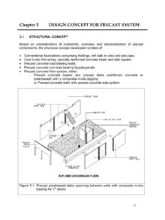
6 F c = specified compressive strength of Concrete at 28 days, based on cylinder tests 4 ksi, for Concrete slab superstructure ksi, for Concrete substructure units fy = 60 ksi, specified minimum yield strength of reinforcement (Grade 60) Es = 29,000 ksi, modulus of elasticity of steel reinforcement LRFD [ ] Ec = modulus of elasticity of Concrete in slab LRFD [ ] = 33,000 K1 (f c)1/2 = 3800 ksi Where: K1 = wc = kcf, unit weight of Concrete n = Es / Ec = 8 LRFD [ ] (modular ratio) Structure Type and slab Depth Prepare preliminary structure data, looking at the type of structure, span lengths, approximate slab depth, skew, roadway width, The selection of the type of Concrete slab structure WisDOT Bridge Manual Chapter 18 Concrete slab Structures July 2018 18-5 (haunched / flat) is a function of the span lengths selected. Recommended span length ranges and corresponding structure type are shown for single-span and multiple-span slabs in Figure Estimated slab depths are shown in Table Currently, voided slab Structures are not allowed.
7 Some of the existing voided slabs have displayed excessive longitudinal cracking over the voids in the negative zone. This may have been caused by the voids deforming or floating-up due to lateral pressure during the Concrete pour. Recent research indicates slabs with steel void-formers have large crack widths above the voids due to higher stress concentrations. If optimum span ratios are selected such that the positive moments in each span are equal, the interior and end span slab depths will be equal, provided Strength Limit State controls. Optimum span ratios are independent of applied live loading. Figure Span Length vs. slab Type For the following optimum span ratio equations based on Strength Limit State controlling, L1 equals the end span lengths and L2 equals the interior span length or lengths, for Structures with three or more spans. WisDOT Bridge Manual Chapter 18 Concrete slab Structures July 2018 18-6 For flat slabs the optimum span ratio is obtained when.
8 The optimum span ratio for a three-span haunched slab results when ) (LL112 = and for a four-span haunched slab when Approximate slab depths for multiple-span flat and haunched slabs can be obtained from Table These values are to be used for dead load computations and preliminary computations only and the final slab depth is to be determined by the designer. (s) Span Length (feet) slab Depth (inches) Haunched 1 Flat 4 20 --- 12 25 --- 14 30 --- 16 35 --- 18 40 --- 20 45 16 2 22 50 2 24 55 19 2 26 60 20 2 --- 65 22 3 --- 70 25 3 --- Table Span Length vs. slab Depth 1 These estimated slab depths at mid-span, apply to interior spans of three or more span Structures , with an end span length of approximately times the interior span.
9 Depths are based on dead load deflection (camber) and live load deflection limits. Haunch length (Lhaunch) = (L2), and dslab / Dhaunch = were used. L2 = interior span length, (dslab) = slab depth in span and (Dhaunch) = slab depth at haunch. Values in table include inch wearing surface. 2 Depths controlled by live load deflection criteria 3 Depths controlled by dead load deflection (camber) criteria 4 These values represent LRFD [ ] recommended minimum depths for continuous-spans using (s+10)/30. The slab span length (s) in the equation and resulting minimum depths are in feet and are presented in inches in Table For simple-spans, the Bureau of Structures adds 10% greater depth and checks the criteria in Values in table include inch wearing surface. WisDOT Bridge Manual Chapter 18 Concrete slab Structures July 2018 18-7 The minimum slab depth is 12 inches.
10 Use increments of inch to select depths > 12 inches. WisDOT Bridge Manual Chapter 18 Concrete slab Structures July 2018 18-8 Limit States Design Method Design and Rating Requirements All new Concrete slab Structures are to meet design requirements as stated in and rating requirements as stated in LRFD Requirements General For Concrete slab design, the slab dimensions and the size and spacing of reinforcement shall be selected to satisfy the equation below for all appropriate Limit States: LRFD [ , ] rniiiRRQQ= = (Limit States Equation) LRFD [ , ] Where: i = load modifier (a function of D , R and I ) LRFD [ , , , ] i = load factor Qi = force effect; moment, shear, stress range or deformation caused by applied loads Q = total factored force effect = resistance factor Rn = nominal resistance; resistance of a component to force effects Rr = factored resistance = Rn The Limit States used for Concrete slab design are: Strength I Limit State Service I Limit State Fatigue I Limit State Statewide Policy Current Bureau of Structures policy is : Set value of load modifier, i , and its factors ( D , R , I ) all equal to for Concrete slab design.