Transcription of WisDOT Bridge Manual Chapter 19 – Prestressed Concrete
1 WisDOT Bridge Manual Chapter 19 Prestressed Concrete January 2017 19-1 table of Contents Introduction .. 3 Pretensioning .. 3 post -Tensioning .. 3 Basic Principles .. 4 Pretensioned Member Design .. 7 Design Strengths .. 7 Loading Stages .. 8 Prestress Transfer .. 8 Losses .. 8 Elastic 8 Time-Dependent 9 Fabrication Losses .. 9 Service Load .. 10 Prestressed I-Girder .. 10 Prestressed Box Girder .. 10 Factored Flexural Resistance .. 11 Fatigue Limit State .. 11 Design Procedure .. 11 Prestressed I-Girder Member Spacing.
2 12 Prestressed Box Girder Member Spacing .. 12 Dead Load .. 12 Live Load .. 13 Live Load Distribution .. 13 Dynamic Load Allowance .. 13 Prestressed I-Girder Deck Design .. 14 Composite Section .. 14 Design Stress .. 15 Prestress Force .. 15 Service Limit State .. 16 Raised, Draped or Partially Debonded Strands .. 17 Raised Strand 18 Draped Strand Patterns .. 18 WisDOT Bridge Manual Chapter 19 Prestressed Concrete January 2017 19-2 Partially Debonded Strand Patterns .. 20 Strength Limit State .. 21 Factored Flexural Resistance.
3 21 Minimum Reinforcement .. 24 Non- Prestressed Reinforcement .. 25 Horizontal Shear Reinforcement .. 25 Web Shear Reinforcement .. 27 Continuity Reinforcement .. 31 Camber and Deflection .. 33 Prestress Camber .. 34 Dead Load Deflection .. 37 Residual Camber .. 38 Prestressed I-Girder Deck Forming .. 38 Equal-Span Continuous Structures .. 39 Unequal Spans or Curve Combined With Tangent .. 40 Construction Joints .. 40 Strand Types .. 40 Construction Dimensional Tolerances .. 41 Prestressed I-Girder Sections .. 41 Prestressed I-Girder Standard Strand Patterns.
4 45 Prestressed Box Girders post - tensioned Transversely .. 45 Available Prestressed Box Girder Sections and Maximum Span Lengths .. 46 Decks and Overlays .. 47 Grout between Prestressed Box Girders .. 47 Field Adjustments of Pretensioning Force .. 48 References .. 50 Design Examples .. 51 WisDOT Bridge Manual Chapter 19 Prestressed Concrete January 2017 19-3 Introduction This Chapter provides information intended for Prestressed I-girders. Prestressed box girders and general Prestressed Concrete guidelines are also included in this Chapter .
5 The definition of Prestressed Concrete as given by the ACI Committee on Prestressed Concrete is: " Concrete in which there has been introduced internal stresses of such magnitude and distribution that the stresses resulting from given external loadings are counteracted to a desired degree. In reinforced Concrete members the prestress is commonly introduced by tensioning the steel reinforcement. This internal stress is induced into the member by either of the following prestressing methods. Pretensioning In pretensioning, the tendons are first stressed to a given level and then the Concrete is cast around them.
6 The tendons may be composed of wires, bars or strands. The most common system of pretensioning is the long line system, by which a number of units are produced at once. First the tendons are stretched between anchorage blocks at opposite ends of the long stretching bed. Next the spacers or separators are placed at the desired member intervals, and then the Concrete is placed within these intervals. When the Concrete has attained a sufficient strength, the steel is released and its stress is transferred to the Concrete via bond.
7 post -Tensioning In post -tensioning, the Concrete member is first cast with one or more post -tensioning ducts or tubes for future insertion of tendons. Once the Concrete is sufficiently strong, the tendons are stressed by jacking against the Concrete . When the desired prestress level is reached, the tendons are locked under stress by means of end anchorages or clamps. Subsequently, the duct is filled with grout to protect the steel from corrosion and give the added safeguard of bond. In contrast to pretensioning, which is usually incorporated in precasting (casting away from final position), post -tensioning lends itself to cast-in-place construction.
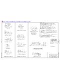
8 WisDOT Bridge Manual Chapter 19 Prestressed Concrete January 2017 19-4 Basic Principles This section defines the internal stress that results from either prestressing method. First consider the simple beam shown in Figure Figure Simple Span Prestressed Concrete Beam The horizontal component, P, of the tendon force, F, is assumed constant at any section along the length of the beam. Also, at any section of the beam the forces in the beam and in the tendon are in equilibrium. Forces and moments may be equated at any section. Figure Assumed Sign Convention for Section Forces The assumed sign convention is as shown in Figure with the origin at the intersection of the section plane and the center of gravity (centroidal axis) of the beam.
9 This convention indicates compression as positive and tension as negative. WisDOT Bridge Manual Chapter 19 Prestressed Concrete January 2017 19-5 The eccentricity of the tendon can be either positive or negative with respect to the center of gravity; therefore it is unsigned in the general equation. The reaction of the tendon on the beam is always negative; therefore the horizontal component is signed as: =cosFP Then, by equating forces in the x-direction, the reaction, P, of the tendon on the Concrete produces a compressive stress equal to: APf1= Where: A = Cross-sectional area of the beam Since the line of action of the reaction, P, is eccentric to the centroidal axis of the beam by the amount e, it produces a bending moment.
10 M = Pe This moment induces stresses in the beam given by the flexure formula: IPeyIMyf2== Where: y = Distance from the centroidal axis to the fiber under consideration, with an unsigned value in the general equations I = Moment of inertia of the section about its centroidal axis The algebraic sum of f1 and f2 yields an expression for the total prestress on the section when the beam is not loaded. IPeyAPfff21p+=+= Now, by substituting I = Ar2, where r is the radius of gyration, into the above expression and arranging terms, we have: +=2prey1 APf These stress conditions are shown in Figure WisDOT Bridge Manual Chapter 19 Prestressed Concrete January 2017 19-6 Figure Calculation of Concrete Stress Due to Prestress Force Finally, we equate forces in the y-direction which yields a shear force, V, over the section of the beam due to the component of the tendon reaction.