Transcription of WisDOT Bridge Manual Chapter 24 – Steel Girder Structures
1 WisDOT Bridge Manual Chapter 24 Steel Girder Structures July 2019 24-1 Table of Contents Introduction .. 5 Types of Steel Girder Structures .. 5 Structural Action of Steel Girder Structures .. 5 Fundamental Concepts of Steel I- girders .. 5 Materials .. 11 Bars and Plates .. 12 Rolled Sections .. 12 Threaded Fasteners .. 12 Bolted Connections .. 13 Quantity Determination .. 14 Design Specification and Data .. 15 Specifications .. 15 Resistance .. 15 References for Horizontally Curved Structures .. 15 Design Considerations for Skewed Supports .. 15 Design Considerations .. 20 Design Loads .. 20 Dead Load .. 20 Traffic Live Load .. 21 Pedestrian Live Load .. 21 Temperature .. 21 Wind .. 21 Minimum Depth-to-Span Ratio .. 21 Live Load Deflections.
2 22 Uplift and Pouring Diagram .. 22 Bracing .. 23 Intermediate Diaphragms and Cross Frames .. 23 End Diaphragms .. 25 Lower Lateral Bracing .. 25 Girder Selection .. 26 Rolled girders .. 26 Plate girders .. 26 WisDOT Bridge Manual Chapter 24 Steel Girder Structures July 2019 24-2 Welding .. 28 Dead Load Deflections, Camber and Blocking .. 32 Expansion Hinges .. 33 Repetitive Loading and Toughness Considerations .. 34 Fatigue Strength .. 34 Charpy V-Notch Impact Requirements .. 35 Non-Redundant Type Structures .. 35 Design Approach - Steps in Design .. 37 Obtain Design Criteria .. 37 Select Trial Girder Section .. 38 Compute Section Properties .. 39 Compute Dead Load Effects .. 40 Compute Live Load Effects .. 40 Combine Load Effects .. 41 Check Section Property Limits.
3 41 Compute Plastic Moment Capacity .. 42 Determine If Section is Compact or Non-compact .. 42 Design for Flexure Strength Limit State .. 42 Design for Shear .. 42 Design Transverse Intermediate Stiffeners and/or Longitudinal Stiffeners .. 43 Design for Flexure Fatigue and Fracture .. 43 Design for Flexure Service Limit State .. 43 Design for Flexure Constructability Check .. 43 Check Wind Effects on Girder Flanges .. 44 Draw Schematic of Final Steel Girder Design .. 44 Design Bolted Field Splices .. 44 Design Shear Connectors .. 44 Design Bearing Stiffeners .. 44 Design Welded Connections .. 44 Design Diaphragms, Cross-Frames and Lateral Bracing .. 45 Determine Deflections, Camber, and Elevations .. 45 Composite Design .. 46 Composite Action .. 46 WisDOT Bridge Manual Chapter 24 Steel Girder Structures July 2019 24-3 Values of n for Composite 46 Composite Section Properties.
4 47 Computation of Stresses .. 47 Non-composite Stresses .. 47 Composite Stresses .. 47 Shear Connectors .. 48 Continuity Reinforcement .. 49 Field Splices .. 51 Location of Field Splices .. 51 Splice Material .. 51 Design .. 51 Obtain Design Criteria .. 51 Section Properties Used to Compute Stresses .. 51 Constructability .. 52 Compute Flange Splice Design Loads .. 53 Factored Loads .. 53 Section Properties .. 53 Factored Stresses .. 53 Controlling Flange .. 54 Flange Splice Design Forces .. 54 Design Flange Splice Plates .. 54 Yielding and Fracture of Splice Plates .. 55 Block Shear .. 56 Net Section Fracture .. 57 Fatigue of Splice Plates .. 57 Control of Permanent Deformation .. 57 Design Flange Splice Bolts .. 58 Shear Resistance .. 58 Slip Resistance.
5 58 Bolt Spacing .. 58 Bolt Edge Distance .. 59 Bearing at Bolt Holes .. 59 Compute Web Splice Design Loads .. 59 WisDOT Bridge Manual Chapter 24 Steel Girder Structures July 2019 24-4 Girder Shear Forces at the Splice Location .. 60 Web Moments and Horizontal Force Resultant .. 60 Design Web Splice Plates .. 60 Shear Yielding of Splice Plates .. 61 Fracture and Block Shear Rupture of the Web Splice Plates .. 61 Flexural Yielding of Splice Plates .. 62 Fatigue of Splice Plates .. 62 Design Web Splice Bolts .. 63 Shear in Web Splice Bolts .. 63 Bearing Resistance at Bolt Holes .. 64 Schematic of Final Splice Configuration .. 65 Bearing Stiffeners .. 67 Plate girders .. 67 Rolled Beams .. 67 Design .. 67 Projecting Width .. 67 Bearing Resistance.
6 68 Axial Resistance .. 69 Effective Column Section .. 69 Transverse Intermediate Stiffeners .. 71 Proportions .. 72 Moment of Inertia .. 72 Longitudinal Stiffeners .. 75 Projecting Width .. 76 Moment of Inertia .. 76 Radius of Gyration .. 77 Construction .. 79 Web 80 Deck Placement Analysis .. 81 Painting .. 89 Floor Systems .. 90 Box girders .. 91 Design Examples .. 93 WisDOT Bridge Manual Chapter 24 Steel Girder Structures July 2019 24-5 Introduction Steel girders are recommended due to depth of section considerations for short span Structures and due to their economy in comparison with other materials or structure types for longer span Structures . Types of Steel Girder Structures This Chapter considers the following common types of Steel Girder Structures : Plate Girder Rolled Girder Box Girder A plate Girder structure is selected over a rolled Girder structure for longer spans or when greater versatility is required.
7 Generally rolled girders are used for web depths less than 36" on short span Structures of 80' or less. Structural Action of Steel Girder Structures Box Girder , rolled Girder and plate Girder bridges are primarily flexural Structures which carry their loads by bending between the supports. The degree of continuity of the Steel girders over their intermediate supports determines the structural action within the Steel Bridge . The main types of structural action are as follows: Simply-supported Structures Multiple-span continuous Structures Multiple-span continuous hinged Structures Simply-supported Structures are generally used for single, short-span Structures . Multiple-span Steel Girder Structures are designed as continuous spans. When the overall length of the continuous structure exceeds approximately 900', a transverse expansion joint is provided by employing Girder hinges and a modular watertight expansion device.
8 The 900 guideline is based on the abutments having expansion bearings and a pier or piers near the center of the continuous segment having fixed bearings. More than one fixed pier shall be used when four or more piers are utilized or when a steep grade (greater than 3%) exists. When one abutment has fixed bearings, see Chapter 12 Abutments for the limitation on the length of a continuous segment. Fundamental Concepts of Steel I- girders This section describes basic concepts of I- Girder sections to aid in understanding the design provisions for Steel I-sections presented in AASHTO LRFD. This section is cursory in nature. WisDOT Bridge Manual Chapter 24 Steel Girder Structures July 2019 24-6 The behavior of non-composite Steel I-section members subject to flexure is similar to the behavior of composite I-section members in negative flexure.
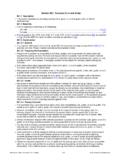
9 A qualitative bending moment versus rotation relationship for a homogeneous compact web section is presented Figure A homogeneous section is defined as a section in which the flanges and web have the same nominal yield strength. In AASHTO LRFD, a compact web section is defined as a non-composite section (or a composite section in negative flexure) that has a web with a slenderness at or below which the section can achieve a maximum flexural resistance, Mmax, equal to the plastic moment, Mp, prior to web bend-buckling having a statistically significant influence on the response. In addition, specific Steel grade, ductility, flange slenderness and lateral bracing requirements must also be satisfied. Compact web sections are typically shallower sections, with thicker webs, than non-compact sections.
10 Compact web sections are often rolled beams or welded Girder sections with proportions similar to rolled beams. Figure Bending Moment versus Rotation for Homogeneous Compact Web Section Proceeding along the actual curve shown in Figure , the initial Stage I behavior represents completely elastic behavior. As the section approaches the theoretical yield moment, My, the presence of residual stresses will result in some inelastic behavior in the outer fibers of the cross section before the calculated My is reached. At Stage II, yielding continues and begins to progress throughout the section as the section approaches the plastic moment, Mp. At Stage III, the entire cross section has yielded; that is, each component of the cross fSTAGE IfSTAGE IIIfSTAGE IIBending MomentRotationMMAX = MpMyIIIIIIU nloadingReloadingActual CurveIdealized Curve WisDOT Bridge Manual Chapter 24 Steel Girder Structures July 2019 24-7 section is assumed to be at Fy.