Transcription of WisDOT Bridge Manual Chapter 36 – Box Culverts
1 WisDOT Bridge Manual Chapter 36 Box Culverts July 2018 36-1 Table of Contents Design Method .. 4 Design Requirements .. 4 Rating Requirements .. 4 Standard Permit Design Check .. 4 General .. 5 Material Properties .. 6 Bridge or Culvert .. 6 Staged Construction for Box Culverts .. 7 Limit States Design Method .. 8 LRFD Requirements .. 8 Limit States .. 8 Load Factors .. 9 Strength Limit State .. 9 Factored Resistance .. 9 Moment Capacity .. 10 Shear Capacity .. 10 Depth of Fill Greater than or Equal to 10 Depth of Fill Less than ft .. 12 Service Limit State .. 12 Factored Resistance .. 12 Crack Control Criteria .. 12 Minimum Reinforcement Check .. 13 Minimum Spacing of Reinforcement .. 14 Maximum Spacing of Reinforcement .. 14 Edge Beams .. 14 Design Loads .. 15 Self-Weight (DC) .. 15 Future Wearing Surface (DW).
2 15 Vertical and Horizontal Earth Pressure (EH and EV) .. 15 Live Load Surcharge (LS) .. 17 Water Pressure (WA) .. 18 Live Loads (LL) .. 18 WisDOT Bridge Manual Chapter 36 Box Culverts July 2018 36-2 Depth of Fill Less than ft.. 18 Case 1 Traffic Travels Parallel to Span .. 18 Case 2 - Traffic Travels Perpendicular to Span .. 20 Depth of Fill Greater than or Equal to ft.. 21 Case 1 Traffic Travels Parallel to Span .. 21 Case 2 Traffic Travels Perpendicular to Span .. 23 Live Load Soil Pressures .. 23 Dynamic Load Allowance .. 23 Location for Maximum Moment .. 23 Design Information .. 25 Detailing of Reinforcing Steel .. 27 Bar Cutoffs .. 27 Corner Steel .. 28 Positive Moment Slab Steel .. 29 Negative Moment Slab Steel over Interior Walls .. 29 Exterior Wall Positive Moment Steel .. 30 Interior Wall Moment Steel.
3 31 Distribution 31 Shrinkage and Temperature Reinforcement .. 32 Box Culvert Aprons .. 33 Type A .. 33 Type B, C, D .. 34 Type E .. 36 Wingwall Design .. 36 Box Culvert Camber .. 37 Computation of Settlement .. 37 Configuration of Camber .. 39 Numerical Example of Settlement Computation .. 39 Box Culvert Structural Excavation and Structure Backfill .. 40 Box Culvert Headers .. 41 Plan Detailing Issues .. 43 Weep Holes .. 43 Cutoff Walls .. 43 WisDOT Bridge Manual Chapter 36 Box Culverts July 2018 36-3 Nameplate .. 43 Plans Policy .. 43 Rubberized Membrane Waterproofing .. 43 Precast Four-Sided Box Culverts .. 44 Three-Sided Structures .. 45 Cast-In-Place Three-Sided Structures .. 45 Precast Three-Sided Structures .. 45 Precast Three-Sided Structure Span Lengths .. 46 Segment Configuration and Skew .. 46 Minimum Fill Height.
4 47 Rise .. 47 Deflections .. 47 Plans Policy .. 48 Foundation Requirements .. 49 Precast Versus Cast-in-Place Wingwalls and Headwalls .. 49 Design Example .. 50 WisDOT Bridge Manual Chapter 36 Box Culverts July 2018 36-4 Design Method Design Requirements All new box Culverts are to be designed using AASHTO LRFD Bridge Design Specifications, hereafter referred to as AASHTO LRFD. Rating Requirements The current version of AASHTO Manual for Bridge Evaluation (LRFR) covers rating of concrete box Culverts . Refer to for additional guidance on load rating various types of Culverts . Standard Permit Design Check New structures are also to be checked for strength for the 190 kip Wisconsin Standard Permit Vehicle (Wis-SPV), with a single lane loaded, multiple presence factor equal to , and a live load factor ( LL) as shown in Table See for the configuration of the Wis-SPV.
5 The structure should have a minimum capacity to carry a gross vehicle load of 190 kips, while also supporting the future wearing surface (where applicable future wearing surface loads are only applied to box Culverts with no fill). When applicable, this truck will be designated as a Single Trip Permit Vehicle. It will have no escorts restricting the presence of other traffic on the culvert, no lane position restrictions imposed and no restrictions on speed to reduce the dynamic load allowance, IM. The maximum Wisconsin Standard Permit Vehicle load that the structure can resist, calculated including current wearing surface loads, is shown on the plans. WisDOT Bridge Manual Chapter 36 Box Culverts July 2018 36-5 General Box Culverts are reinforced concrete closed rigid frames which must support vertical earth and truck loads and lateral earth pressure.
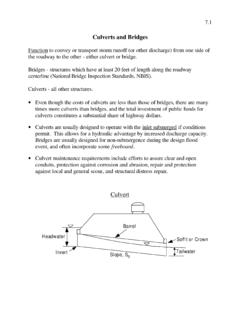
6 They may be either single or multi-cell. The most common usage is to carry water under roadways, but they are frequently used for pedestrian or cattle underpasses. Box Culverts used to carry water should consider the following items: Hydraulic and other requirements at the site determine the required height and area of the box. Hydraulic design of box Culverts is described in Chapter 8. Once the required height and area is determined, the selection of a single or multi-cell box is determined entirely from economics. Barrel lengths are computed to the nearest 6 inches. For multi-cell Culverts the cell widths are kept equal. A minimum vertical opening of 5 feet is desirable for cleaning purposes. Pedestrian underpasses should consider the following items: The minimum opening for pedestrian underpasses is 8 feet high by 10 feet wide. However, when considering maintenance and emergency vehicles or bicyclists the minimum opening should be 10 feet high by 12 feet wide.
7 For additional guidance refer to the Wisconsin Bicycle Facility Design Handbook and the FDM. The entire top and 1 foot below the bottom of the top slab should be waterproofed. The top of the bottom slab should be sloped with a 1% normal crown to minimize moisture collecting on the travel path. Additionally, to 1% longitudinal slope for drainage is recommended. Flared wings are recommended at openings. For long underpasses, lighting systems (recessed lights and skylights) should be considered, as well. For additional guidance on user s comfort, safety measures, and lighting refer to the Wisconsin Bicycle Facility Design Handbook. Cattle underpasses should consider the following items: The minimum size for cattle underpasses is 6 feet high by 5 feet wide. Consider providing a minimum longitudinal slope of 1%, desirable 3%, to allow for flushing, but not so steep that the stock will slip.
8 Slopes steeper than 5% should be avoided. For additional guidance refer to the FDM. Aluminum box Culverts are not permitted by the Bureau of Structures. WisDOT Bridge Manual Chapter 36 Box Culverts July 2018 36-6 Figure Typical Cross Sections Material Properties The properties of materials used for concrete box Culverts are as follows: f'c = specified compressive strength of concrete at 28 days, based on cylinder tests = ksi for concrete in box Culverts fy = 60 ksi, specified minimum yield strength of reinforcement (Grade 60) Es = 29,000 ksi, modulus of elasticity of steel reinforcement LRFD [ ] Ec = = modulus of elasticity of concrete in box LRFD [ ] (33,000)(K1)(wC) (f C)1/2 = 3586 ksi Where: K1 = WC = kcf, unit weight of concrete n = Es / Ec = 8, modular ratio LRFD [ ] Bridge or Culvert Occasionally, the waterway opening(s) for a highway-stream crossing can be provided for by either culvert(s) or Bridge (s).
9 Consider the hydraulics of the highway-stream crossing system in choosing the preferred design from the available alternatives. Estimates of life cycle costs and risks associated with each alternative help indicate which structure to select. Consider construction costs, maintenance costs, and risks of future costs to repair flood damage. Other considerations which may influence structure-type selection are listed in Table WisDOT Bridge Manual Chapter 36 Box Culverts July 2018 36-7 Bridges Advantages Disadvantages Less susceptible to clogging with drift, ice and debris Require more structural maintenance than Culverts Waterway width increases with rising water surface until water begins to submerge structure Piers and abutments susceptible to scour failure Natural bottom for waterway Susceptible to ice and frost forming on deck Culverts Grade rises and widening projects sometimes can be accommodated by extending culvert ends Silting in multiple barrel Culverts may require periodic cleanout Minimum structural maintenance No increase in waterway area as stage rises above top of culvert Usually easier and quicker to build than bridges May clog with drift.
10 Debris or ice Table Advantages/Disadvantages of Structure Type Staged Construction for Box Culverts The inconvenience to the traveling public has often led to staged construction projects. Box Culverts typically work well with staged construction. Any cell joint can be used for a staging joint. When the construction staging line cannot be determined in design to locate a cell joint, a contractor placed construction joint can be done with an extra set of dowel bars and the contractor field cutting the longitudinal bars. WisDOT Bridge Manual Chapter 36 Box Culverts July 2018 36-8 Limit States Design Method LRFD Requirements For box culvert design, the component dimensions and the size and spacing of reinforcement shall be selected to satisfy the following equation for all appropriate limit states, as presented in LRFD [ ]: Q = i i Qi Rn = Rr Where: i = Load modifier (a function of D, R, and i) i = Load factor Qi = Force effect: moment, shear, stress range or deformation caused by applied loads Q = Total factored force effect = Resistance factor Rn = Nominal resistance: resistance of a component to force effects Rr = Factored resistance = Rn See for load modifier values.