Transcription of Working 160M From a Small Lot (and Larger Ones Too)
1 Working 160m From a Small Lot(and Larger ones Too)Jim Brown What Happens on 160m ? Contests, mostly during winter, mostly CW, one SSB Rag-chewing, especially SSB JT65A (USB, set dial to 1838 kHz) Work DX year round Summer has QRN, but best time to work VK/ZL, South America 160m Is a Tough Band Propagation quite variable, signals often not very strong, heavy QRN during the summer Mostly a nightime band, varies a lot through the night During the winter, 800 miles or more is possible 2 hours before sunset, 2 hours after sunrise 160m Is a Tough Band Wavelength makes antennas more difficult Quarter-wave vertical is 130 Ft Half-wave dipole is 260 Ft, and it s low at only 130 ft Verticals need radials or a counterpoise.
2 And they work best if they re fairly large What It Takes Verticals rule on 160m Taller is better Top loading is a very good thing Radials or a counterpoise are critical Don t let the perfect be the enemy of the good Good Vertical Antennas A straight quarter-wave (Best) /4 ~ 125 ft at 1830 kHz with THHN Inverted L (Good) Go straight up as high as you can with a wire, then bend the remaining wire to run horizontal to resonate it Tee vertical (A bit better than L) Like an inverted L, but the top is extended in opposite directions Inverted L Simple Tee Vertical Other Vertical Radiators Shortened vertical with multiple top loading wires (capacity hat) Shortened vertical with capacity hat and bottom loading coil Shortened vertical with bottom loading coil Heliacal wound vertical (K6MM) What is Loading?
3 Loading is the modification of a short antenna so it looks longer to the transmitter (often resonant) Add series inductance At bottom or center of radiator Add horizontal wire(s) at the top Wires provide capacitance to earth What is Top Loading? Bend top over (inverted L) Bend top both ways (Tee vertical) Add multiple wires to top Connect top guy wires to tower Length of guys to first insulator provides top loading Yagis on top of a tower add top loading (not insulated elements) Why Top Loading Is Best Radiation is produced by current Current in a resonant vertical peaks near the feedpoint, and is zero at the far end Adding inductance near a current peak breaks it up and reduces radiation Added resistance near feedpoint burns more power (R of inductor)
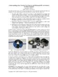
4 Using Bottom Loading Bottom loading at the base works, but burns some power Using bigger wire helps (#10 good) In the recent Stew Perry, N6 NUL worked JA with 100 watts using an inverted L only about 35 ft tall designed for 80M, adding just enough coil at the base that his K2 auto tuner could load it! (It helps that he s near the harbor in Santa Cruz.) Making a Shorter Wire Resonant Use insulated wire (1-2%) Make the conductor thicker 2 or 3 wires spaced 6-12 inches apart, connected top and bottom (1-2%) Improves SWR bandwidth Not a lot, but every little bit helps Good Inductors Are Easy wind #10 THHN solid copper around 3-in or 4-in PVC conduit Drill holes for wires at each end to hold in place Extend wires to screws mounted to either end Drill more holes for antenna wires Loop antenna wire through holes, connect both wires at screws 160m Loading Coil 7 H Feedpoint of Sloping Vertical Good Inductors Are Easy Use NEC to model antenna and predict inductance required to resonate the the antenna or.
5 Use Vector Analyzer to measure feedpoint Z of an existing antenna that s too short, export data to SimSmith and predict inductance Coil winding formulas in ARRL Handbook are very accurate How Much Top Loading? Use NEC to predict Even a very simple model will get you close for the radiator Connect the bottom of the vertical wire to ground, add a source at the bottom, add the top loading wire(s) Plot SWR in 10 kHz steps to find resonance Vary length of top wire(s) to set FR Top Loading Guidelines Make the vertical as tall as you can for best efficiency Do what you can with left-over wire length at the top, either T or L Add loading coil at base if needed to make it easier to tune For an Inverted L, making the total wire length = /4 = 130 ft will get you close How Earth Affects Verticals Power is lost in earth very near the antenna before it can be radiated Radials, counterpoise reduce this loss Radials.
6 Counterpoise make the most difference with poor soil How Earth Affects Verticals Radiated signal is reflected by the earth far from the antenna Reflection adds to direct signal Shapes the vertical pattern Better soil helps low angle most Radials don t help the reflection, but they strengthen the radiated signal that gets reflected What Kind of Soil Do I Have? Most of the Bay Area has Average soil Most of the North Bay has Good soil Most desert and very rocky areas are poor to very poor soil You can measure it see N6LF s website for a simple method The Power of Earth Reflections Salt WaterVery Good SoilAverage SoilRocky/Sandy Soil-10 -5 0dB0dB-5-10-15 Vertical Pattern Resistance Matters Radiation resistance (RR)
7 Is the part of the feedpoint impedance that accounts for radiated power Mostly determined by vertical height of the radiator RR is good resistance, Larger is good /4 /8 Radiation Resistance vs Height Resistance Matters Ground resistance (RG) combines with wire resistance (RW) to burn transmitter power It s A Simple Series CircuitRRRWRGCURRENT RADIATED POWERWIRE LOSS GROUND LOSS Loss Resistance Matters PTRANS = PRAD+PWIRE+PGROUND PTRANS = I2RR + I2RW + I2RG antenna Efficiency = RR/(RW+RG) If (RW+RG) = RR, loss is 3dB If (RW+RG) = 2RR, loss is 6dB We want large RR , Small RG Ground Resistance Depends on the nature of the earth around the antenna We can t change it except by moving Depends on the radial system Make RG smaller by using more radials and longer radials a good counterpoise a ground screen Tall antenna , Good RadialsR W = 1 RG = 7 CURRENTRADIATED POWERWIRE LOSSGROUND LOSSRR = 34 Loss = Tall antenna , Good RadialsR W = 1 RG = 7 100 W81 W17 WRR = 34 Loss = Short antenna , Limited RadialsR W =.
8 5 RG = 30 CURRENT RADIATED POWERWIRE LOSSGROUND LOSSRR = 6 Loss = 15 dB Short antenna , Limited RadialsR W = .5 RG = 30 100W 17 Watt82 WattsRR = 6 Loss = dB Typical Loss Resistances RW of #10 wire ~1 for /4 It s hard to get RG below 10 on a lot of land, and 20 is tough on a Small lot So ignore RW (use big wire) and concentrate on trying to make RG smaller and RR Larger Why Radials or Counterpoise? Earth is a relatively poor conductor that is, it s a (very big) resistor Even the best connection to earth is bad for an antenna it drives current to that lossy earth Current in lossy earth burns transmitter power (PG = I2RG ) before it can be radiated Why Radials or Counterpoise?
9 An ideal radial system: shields the antenna from the earth provides a path for return current Provides a return path for fields produced by the antenna A counterpoise provides only the return path More about counterpoises later Why Radials or Counterpoise? With no radials or counterpoise, the outside of the coax forms a single radial or counterpoise It s better than nothing, but not very effective And it can put RF in the shack Guidelines for All Radials Insulated wire holds up longer #18 minimum size for durability Large spools hard to buy #14 THHN (house wire) works well Mass market items often less expensive and easy to find Discount for 6 or more spools at big box stores (Home Depot, Lowe s) On-Ground Radial Systems Best up to 60 /4 wires (shortened by VF to 100 ft)
10 Laid out as symmetrically as you can Very Good many wires on the ground, lengths can be random Symmetry is good, but most radial systems must be shorter in some directions because they run into buildings, roads, property lines Resonant Radial Length1830 kHz Average Soil Velocity Factor (VF) vs Height Traditional Radial Systems 60 radials, each 100 125 ft long, arranged symmetrically around the feedpoint That requires that we can rig our antenna in the center of open space with a 100 ft radius Traditional Radial Systems 60 radials, each 100 125 ft long, arranged symmetrically around the feedpoint That requires that we can rig our antenna in the center of open space with a 100 ft radius Show of hands how many can do this?