Transcription of WORKSHOP MANUAL - samangan-a.ru
1 WORKSHOP MANUALNKR . NPR . NQRANTI-LOCK brake system (ABS)SECTION 5A4 anti -LOCK brake system (ABS) 5A4-1 SECTION 5A4 anti -LOCK brake system (ABS)Service PrecautionCAUTION: Always use the correct fastener in the proper location. When you replace a fastener, use ONLYthe exact part number for that application. ISUZU will call out those fasteners that require a replacementafter removal. ISUZU will also call out the fasteners that require thread lockers or thread sealant. UNLESSOTHERWISE SPECIFIED, do not use supplemental coatings (Paints, greases, or other corrosion inhibitors)on threaded fasteners or fastener joint interfaces. Generally, such coatings adversely affect the fastenertorque and the joint clamping force, and may damage the fastener.
2 When you install fasteners, use thecorrect tightening sequence and specifications. Following these instructions can help you avoid damage toparts and Precaution .. 5A4-1 General Description .. 5A4 -5 system Components .. 5A4 -6 Electronic Hydraulic Control Unit (EHCU) .. 5A4 -6 Hydraulic Unit (HU) .. 5A4 -6 ABS Warning Light .. 5A4 -6 Wheel Speed Sensor .. 5A4 -6 Normal and anti -lock 5A4 -6 brake Pedal 5A4 -7 Acronyms and Abbreviations .. 5A4 -7 General Diagnosis .. 5A4-7 General 5A4 -7 ABS Service Precautions .. 5A4 -7 Computer system Service Precautions .. 5A4 -7 General Service Precautions .. 5A4 -8 Note on 5A4 -8 Test Driving ABS Complaint 5A4 -8 ABS Warning 5A4 -8 Normal Operation.
3 5A4 -8 Basic Diagnostic Flow Chart .. 5A4 -9 Basic Inspection 5A4 -95A4-2 anti -LOCK brake system (ABS)Tech 2 Scan Tool .. 5A4 -10 Tech 2 Features .. 5A4 -11 Getting Started .. 5A4 -11 Operating Procedure (For Example) .. 5A4 -12 DTC Modes .. 5A4 -13 DTC Information Mode .. 5A4 -13 Plotting Snapshot 5A4 -14 Plotting Graph Flow Chart (Plotting graph after obtaining vehicle information) .. 5A4 -15 Flow Chart for Snapshot Replay (Plotting Graph) .. 5A4 -16 Tech 2 Data Display .. 5A4 -17 Special Function .. 5A4 -17 EHCU Connector Pin-out 5A4 -21 Circuit Diagram .. 5A4 -22 Connector List .. 5A4 -26 Part Location .. 5A4-29 Symptom Diagnosis .. 5A4 -30 Chart A-1 ABS Works Frequently But Vehicle Does Not Decelerate.
4 5A4 -30 Chart TA-1 ABS Works Frequently But VehicleDoes Not Decelerate (Use TECH 2) .. 5A4 -30 Chart A-2 Uneven Braking Occurs While ABS Works .. 5A4 -31 Chart A-3, TA-3 The Wheels Are 5A4 -31 Chart A-4 brake Pedal Feed Is Abnormal .. 5A4 -32 Chart A-5, TA-5 Braking Sound (From Hydraulic Unit)Is Heard While Not 5A4 -33 Diagnostic Trouble Codes .. 5A4 -34 Diagnosis By ABS Warning Light Illumination Pattern .. 5A4 -35 Diagnostic Trouble Codes (DTCs).. 5A4 -35 Chart B-1-1 With the key in the ON position (Before starting the engine).Warning light (W/L) is not activated.. 5A4 -39 Chart 1 (DTC 13/C0213) Vehicle Type 5A4 -40 Chart 2 (DTC 14/C0214) Low Power Voltage ofRear Sensor or EHCU Abnormality.
5 5A4 -40 Chart 3 (DTC 15/C0215) Low Power Voltage OUT of Range .. 5A4 -41 Chart 4 (DTC 25/C0225) Exhaust brake Cut Circuit Abnormality .. 5A4 -42 Chart 5 (DTC 33/C0233) Motor Drive Circuit Abnormality .. 5A4 -42 anti -LOCK brake system (ABS) 5A4-3 Chart 6 (DTC 34/C0234) Abnormal Motor Rotation .. 5A4 -42 Chart 7 (DTC 41/C0241) Solenoid Valve Power Supply Abnormality .. 5A4 -43 Chart 8 (DTC 43, 45/C0243, C0245) Solenoid Valve Circuit Abnormality .. 5A4 -43 Chart 9 (DTC 51/C0251) FL Speed Sensor Circuit Abnormality .. 5A4 -43 Chart 10 (DTC 52/C0252) FR Speed Sensor Circuit 5A4 -43 Chart 11 (DTC 53/C0253) RL Speed Sensor Circuit 5A4 -44 Chart 12 (DTC 54/C0254) RR Speed Sensor Circuit Abnormality .. 5A4 -45 Chart 13 (DTC 61/C0261) Abnormal FL Speed Sensor 5A4 -46 Chart 14 (DTC 62/C0262) Abnormal FR Speed Sensor Signal.
6 5A4 -48 Chart 15 (DTC 63/C0263) Abnormal RL Speed Sensor Signal .. 5A4- 50 Chart 16 (DTC 64/C0264) Abnormal RR Speed Sensor 5A4- 51 Chart 17 (DTC 65/C0265) Tire Size 5A4- 52 Unit Inspection 5A4- 53 Chart C-1-1 FL Speed Sensor Output Inspection Procedure .. 5A4- 53 Chart C-1-2 FR Speed Sensor Output Inspection 5A4- 54 Chart C-1-3 RL Speed Sensor Output Inspection 5A4- 55 Chart C-1-4 RR Speed Sensor Output Inspection Procedure .. 5A4- 57 Chart TC-1 Sensor Output Inspection Procedure (Use TECH 2) .. 5A4- 58 Electronic Hydraulic Control Unit (EHCU).. 5A4- 5A4- 59 Front Speed Sensor .. 5A4- 60 Front Speed Sensor and Associated Parts .. 5A4- 5A4- 60 Inspection and Repair .. 5A4- 60 Front Speed Sensor Rotor.
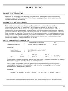
7 5A4- 61 Front Speed Sensor Rotor and Associated Parts .. 5A4- 5A4- 61 Inspection and Repair .. 5A4- 62 Rear Speed Sensor .. 5A4- 63 Rear Speed Sensor and Associated 5A4- 5A4- 64 Inspection and Repair .. 5A4- 645A4-4 anti -LOCK brake system (ABS) 64 Rear Speed Sensor Rotor .. 5A4- 65 Rear Speed Sensor Rotor and Associated Parts .. 5A4- 5A4- 65 Inspection and Repair .. 5A4- 65 Special Tools .. 5A4- 67 anti -LOCK brake system (ABS) 5A4-5 General DescriptionThe anti -lock brake system (ABS) works on all fourwheels. A combination of wheel speed sensor andElectronic Hydraulic Control Unit (EHCU) candetermine when a wheel is about to stop turning andadjust brake pressure to maintain best system helps the drive maintain greater control ofthe vehicle under heavy braking CONTROLLEROREXH brake CUT RELAY5744135TO EHCUEHCUELECTRONIC HYDRAULICCONTROL UNIT(EHCU)HYDRAULIC UNIT(HU)296 ABSDIAGTO EHCUCAB10TO EHCUL egend(1) Hydraulic Line(7) Load Sensing Proportioning Valve (LSPV)(2) Electronic Line(8) Battery(3) Electronic Hydraulic Control Unit (EHCU)(9) ABS Warning Light(4) Front Wheel Speed Sensor(10) brake Switch(5) Rear Wheel Speed Sensor(6) Diagnosis Connector5A4-6 anti -LOCK brake system (ABS)
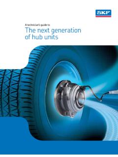
8 system ComponentsThe anti -lock brake system consists of a ElectronicHydraulic Control Unit (EHCU), four Wheel SpeedSensors and Warning Hydraulic Control Unit (EHCU)The EHCU consists of Electronic brake ControlModule (EBCM) and Hydraulic Unit (HU).The EHCU is located at the frame side, in front of rearspring EHCU consists of ABS control circuits, faultdetector, and a fail-safe. It drives the hydraulic unitaccording to the signal from each sensor, cancellingABS to return to normal braking when a malfunctionhas occurred in the EHCU is self-diagnosing function which canindicate faulty circuits during lockLeverMove lever outsideEHCUCONNECTORNOTE:When disconnecting harness connector from EHCU,push the tang lock of the connector ( portion) andrelease the tang lock.
9 Then move the Unit (HU)It consists of a Motor, Plunger Pump, Solenoid Valvesand Check Valves: Reduces or holds the caliper fluidpressure for each front disc brake or both rear drumbrakes according to the signal sent from the : Temporarily holds the brake fluid thatreturns from the front and rear wheel brake so thatpressure of front wheel brake can be Pump: Feeds the brake fluid held in thereservoir to the master : Drives the pump according to the signal fromEHCU. Check Valve: Controls the brake fluid Warning LightVehicles equipped with the anti -lock brake Systemhas an amber ABS warning light in the instrumentpanel. The ABS warning light will illuminate if amalfunction in the anti -lock brake system is detectedby the Electronic Hydraulic Control Unit (EHCU).
10 Incase of an electronic malfunction, the EHCU will turn ON the ABS warning light and disable the anti -lockbraking ABS light will turn ON for 2 seconds after theignition switch is to the ON position, and then will the ABS light comes ON and stays ON whiledriving, the anti -lock brake system should beinspected for a malfunction according to the Speed SensorIt consists of a sensor and a rotor. The sensor isattached to the knuckle on the front wheels and to thebracket on the brake back plate on the rear front speed sensor is coil type and rear is Hall sensor rotors press-fitted to front and rear wheelhubs output pulse frequency depending on speed sensors find vehicle speed from and anti -lock BrakingUnder normal driving conditions, the anti -lock BrakeSystem functions the same as a standard powerassisted brake system .