Transcription of WSPR 2.0 User’s Guide - Princeton University
1 WSPR User s Guide Joe Taylor, K1JT Overview WSPR (pronounced "whisper") stands for Weak Signal Propagation Reporter. The WSPR software is designed for probing potential radio propagation paths using low-power beacon-like transmissions. WSPR signals convey a callsign, Maidenhead grid locator, and power level using a compressed data format with strong forward error correction and narrow-band 4-FSK modulation. The protocol is effective at signal-to-noise ratios as low as 28 dB in a 2500 Hz bandwidth. Receiving stations with internet access may automatically upload reception reports to a central database. The WSPRnet web site provides a simple user interface for querying the database, a mapping facility, and many other features. System Requirements SSB receiver or transceiver and antenna Computer running the Windows, Linux, FreeBSD, or OS X operating system. GHz or faster CPU and at least 100 MB of available RAM Monitor with at least 800 x 600 resolution Sound card supported by your operating system and capable of 48 kHz sample rate If you will transmit as well as receive, an interface using a serial port to key your PTT line or a serial cable for CAT control.
2 Linux and FreeBSD versions can also use a parallel port for PTT. Alternatively, you can use VOX control. Audio connection(s) between receiver/transceiver and sound card A means for synchronizing your computer clock to UTC Basic Operating Instructions The following steps should get you on the air quickly with WSPR. 1. Download WSPR from the WSJT Home Page, Click on the WSPR link at the left margin and then on the appropriate download link. Install the program in the usual way for your computer platform. Under Windows, execute the downloaded file and follow the installation instructions. See page 8 for other operating systems. 2. Connect appropriate interface cables between radio and computer. For help with the hardware interface, refer to one of the many HowTo s for sound card modes, for example In general, you will need to connect the radio s audio output to the computer s soundcard input; for receive-only systems, that s all you need!
3 If you will also be transmitting you must patch soundcard output to the radio s microphone or data input. For T/R switching and CAT control you may need a serial data cable or cables. 1 3. Start WSPR by double-clicking on its desktop icon or another method of your choice. On the Setup | Station parameters dialog screen enter your callsign and 6-digit grid locator, select audio input and output devices, and select your transmitter power in dBm. (See Appendix A for a Watts-to-dBm conversion table.) Use the nearest value from the drop-down list. SWLs should provide a unique identifier (up to 8 characters) in place of a callsign. 4. If you choose to transmit as well as receive, WSPR will control your T/R sequencing. Select the desired PTT method (DTR, RTS, CAT, or VOX). For DTR- or RTS-controlled switching, select a PTT port. For receive-only or VOX-controlled systems, set PTT port to None. 5. WSPR offers limited CAT control of your transceiver, usable for T/R switching and frequency setting.
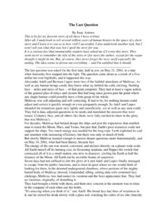
4 To use this feature check Enable CAT and fill in the remaining parameters on the Station parameters screen. Consult the manual for your radio to determine necessary parameter values for the serial connection. 6. You may confirm proper operation of the WSPR decoder by opening a sample audio file recorded by WSPR. Select File | Open, navigate to the ..\save\Samples directory under the installation directory, and open the file A total of six WSPR signals should be decoded, and your screen should look like the image on the next page. (You might find it interesting to listen to the sample file using Windows Sound Recorder or a similar utility program. The WSPR signals are barely audible, if audible at all, and the recording includes many atmospheric static and yet WSPR decodes the signals without errors.) 7. Select an operating band from the Band menu. The default WSPR frequency will appear in the Dial frequency box. For example, you should see MHz for the 30 m band.
5 Set your transceiver to this frequency in USB or a USB-based data mode. (If you enabled CAT control, the frequency setting should be automatic.) Select a desired Tx frequency by double-clicking somewhere in the graphical display area. Available Tx frequencies fall in the range 1400 1600 Hz above the dial frequency. Clicking near the bottom of the graphical area gives a frequency near the lower limit, and clicking near the top puts you near the upper limit. 8. WSPR uses two-minute time slots for transmitting and receiving. The slider labeled Tx fraction sets the average proportion of time allocated for transmitting. The default setting of 20% is a good compromise under typical conditions: it means that you will transmit approximately once every ten minutes and receive the rest of the time. The exact T/R sequence will be randomized so as to maximize your chances of receiving other WSPR stations. For receive-only operation, set the Tx fraction slider to zero.
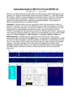
6 9. While in Idle mode, you may click the Tune button to produce a short unmodulated test transmission. Duration of the transmission (in seconds) is set by the Tx fraction slider. 2 10. Be sure that your computer clock is correct to within about 1 second. Many operators synchronize with an Internet time service and software such as Dimension 4 for Windows, available at For Ubuntu Linux install ntp, select System | Administration | Time and Date, choose a couple of time servers near you, and select Automatic Synchronization. 11. If you have internet access and wish to upload your reports automatically to WSPRnet, check the box labeled Upload spots. 12. To begin normal operation, clear the Idle checkbox. WSPR will then begin a receive sequence at the start of the next even-numbered UTC minute. After reception has started, use the computer s sound mixer and/or the volume controls on your radio or soundcard interface to adjust the audio level (lower left corner of main WSPR screen, see picture on next page) to about 0 dB.
7 At the end of each reception interval, the waterfall will update and any decoded WSPR transmissions will appear in the main text window. 3 Additional Details Main Screen In normal operation your WSPR screen will look something like the screen shot shown above. The decoder looks for all detectable WSPR signals in a 200 Hz passband and displays its results in a waterfall spectrogram, a text window, and a Band Map. The spectrogram covers a narrow frequency range (slightly more than 200 Hz) in the vertical direction; the last three digits of the received frequency, in Hz, are displayed on a scale at right. Time runs from left to right in the spectrogram. On a typical computer screen each two-minute interval is a strip about 1 cm wide. The times of your own transmissions are denoted by thin green vertical lines in the spectrogram. Each decoded WSPR signal produces text showing the UTC, measured signal-to-noise ratio in dB (in a 2500 Hz reference bandwidth), time offset DT in seconds, measured frequency in MHz, drift rate in Hz/minute, and the decoded message itself.
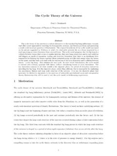
8 4 Time offsets greater than about 2 seconds may indicate a significant clock error at transmitter or receiver, or possibly both. For best performance your computer clock should be kept accurate to within 1 second. Apparent frequency drifts greater than 1 Hz per minute most often occur at the transmitter, and should be corrected if possible. Of course, receiver drifts could also contribute to a measured drift but they are easily recognized because nearly all signals will then appear to drift by the same amount. Color coding is used in the Band Map to indicate elapsed time since any station was decoded. Calls in red have been seen within 15 minutes of the last line of decoded text; yellow callsigns are 15-30 minutes old, light gray 30-45 minutes, and darker gray 45-60 minutes. Callsigns more than an hour older than the most recent one are removed from the Band Map. Station Parameters The Station parameters dialog is mostly self-explanatory. compound callsigns such as PJ4/K1 ABC, W7/VE3 DEF, and even WA2 XYZ/37 are permitted but should be used only when necessary.
9 Doubly compounded callsigns such as PJ4/K1 ABC/P are not supported. See Appendix B for further details. As illustrated in the example above, it is permissible to use one serial port for T/R switching (via the DTR or RTS line) and a second serial port for CAT control of the radio s dial frequency. Consult the operator s manual for your radio to determine correct parameters for CAT control, including Serial rate, Data bits, Stop bits, and Handshake method. With the exception of callsign and grid locator, it is generally best to use values from the drop-down lists rather than typing parameters from the keyboard. 5 Advanced Setup The Advanced dialog can be called up from the Setup menu or by typing F7. If your licensing authority requires callsign identification in Morse code at specified intervals, you may set the interval in the CW ID field. Your callsign will then be sent in CW at the end of WSPR transmissions, at the specified interval. Because CW at 25 wpm uses several times more bandwidth than a WSPR signal, it is strongly recommended that you not use the CW ID feature unless required to do so.
10 Users of homebrew receiving equipment may require a different BFO frequency than the standard 1500 Hz used for SSB transceivers. You can enter a nonstandard value in the field labeled Rx BFO (Hz). Many modern transceivers use a master oscillator from which most other frequencies are synthesized. If the master oscillator is slightly off frequency, all dial readings may be high or low in a predictable way. Appendix C outlines a simple procedure for determining whether your radio can be calibrated in this way, and if so how to determine the calibration constants A and B. Then, if you are using CAT control, you can improve the accuracy of your transmitted and received frequencies by entering these values and checking Enable frequency correction on the Advanced setup screen. Frequencies sent to the radio will then be adjusted according to your calibration constants. The button labeled Measure an audio frequency may be useful in determining values for A and B.