Transcription of www.jawamoped.com JawaMoped Electrics – Contact less ...
1 JawaMoped Electrics Contact less ignition Systems. The Jawa / Babetta moped ignition systems are about as simple as you can get, as a result there is very little to go wrong. They were very advanced for their time, being the first mopeds in the world to be equipped with fully electronic, Contact less ignition systems. Apart from regular spark plug cleaning or replacement, there is nothing that requires any maintenance or adjustment in the normal care of the moped. A few very late models had a more modern 12 volt system, see later in this sheet for details. I am talking here about the true mopeds types 28, 207, 210. 225 etc., as the scooters & Mustang bikes, models 20, 21 and 23, are a little more complicated & more like a proper bike, with points that need cleaning and adjusting from time to time.
2 Thanks are due to for some of the information in this data sheet from their web site. Warning:- All vehicle ignition systems operate at several thousand volts, when checking the spark, hold the plug by insulated pliers. Dirt, moisture or damage on the plug cap or leads can cause the sparks to track to the outside and a kick from the ignition can be very unpleasant. People with electronic heart pacemakers especially, should stay away from vehicle ignition voltages. System description The generator is a permanent magnet alternator, the rotor, the solid drum in the centre, having a series of permanent magnets and so doesn t need a slip ring, commutator, brushes or coils to generate the magnetic field. The stator, the static ring around the outside of the rotor, has 4 coils attached to it, three of these are for lighting and auxiliary circuits but the upper most one is the ignition coil.
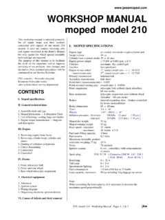
3 The Alternating Current that this generates powers the ignition unit. One end of the coil is connected, by the red wire, to the G terminal of the ignition unit, the other end being connected to the moped frame. Behind the ignition coil as part of the stator ring is the pulse forming coil that senses the position of the rotor and fires the ignition unit via a white or a yellow impulse wire connected to the I terminal, (see below for details of the two types) which creates the spark at the correct position of the piston. ignition unit types fig. 1 fig. 2 fig. 3 fig. 4 Fig. 1:- The red Transimo one part combined transistor ignition unit & coil was fitted to model 28s and early 207s and is probably the most troublesome of all the units.
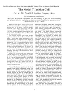
4 Any of these still in use would be at least 25 years old now. This part is no longer available although the thyristor semiconductor itself, the round silver device next to the connectors, is replaceable with a Tesla KD602 if you can find one. Re-solder the two wires to the new transistor, the right way round, and refit it with the two little screws. A better bet is to replace the complete unit with a newer version see below. Fig. 2:- The black Thyristor ignition unit with 4 round prong connectors used on later 207s and most 210s is a better unit. The plastic bodies of these shrink and crack with age but this doesn t seem to affect the operation. These are still available new. The only down side is that they need a separate 4 volt HT coil (a round silver unit) to power the spark plug.
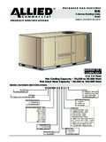
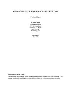
5 See below for a guide to checking these units or even for details of how to make your own ! Fig. 3:- A Hungarian made, one part combined thyristor ignition unit & coil with 3 blade connectors and an HT connector for screwing in the plug lead, used on 225s and later mopeds, is the best of the bunch. Small and easy to fit and wire up, doesn t need a separate coil, and still available new. These can be used to replace all of the other three types see details below. Fig. 4:- A Czech Republic made combined thyristor ignition unit & coil with just 2 blade terminals and a metal mounting lug, seem to have been fitted to some of the final Stella type mopeds. These can cause trouble when their earth connection through the mounting bracket corrodes. As a result of a bad ground connection the unit burns internally and fails.
6 Checking -- Spark and Wiring The usual way of checking if the ignition system is working is to remove the plug from the cylinder & re-connect it to the plug lead, then holding the metal body of the plug against bare metal, say the cylinder fins, kick the engine over. You should be able to see a spark jump across between the plug electrodes. The plug may have to be shaded from bright light to be able to see the spark clearly. A spark here doesn t guarantee correct sparking under conditions inside the cylinder, but a good strong regular spark is a good indication that the ignition system is working OK. However, a possible problem is the ignition unit failing or going intermittent because of overheating during use. If you are getting no spark or an irregular spark, there could be a faulty component in the system.
7 First always check the components are wired up correctly against the appropriate wiring diagram which you can 1 of 5 -- Coil, Thyristor and Stator get from my manuals page. Down-load the one for your type of ignition unit and with the same accessories fitted. Don t assume the wiring colours in your moped are the same as the diagram, sometimes different colours might be used in the factory or a previous owner might have changed some wires. If you are in any doubt, follow the colours through to find both ends match up to the correct connection points against the relevant wiring diagram. Check all terminals are clean & tight, if new terminals have been fitted anywhere, make sure they are making good Contact , old wire can corrode inside the insulation & stop a new connector making Contact with the wire.
8 If fitting new terminals, scrape the corroded wire back first to reveal bright metal. If your wiring is a particular mess it might be an idea to just remove the lot and temporarily re-wire the ignition circuit only for testing, as in my ignition wiring data sheet, to eliminate any source of problems, short circuits etc., with the lighting and auxiliary circuits, which can be reconnected after. -- Spark Plug and HT On all two strokes it is always best to try a new spark plug first, carbon build up or oiling can stop the plug working properly after only a short mileage. Recommended plug type is PAL N7R (see my spark plug data sheet for other brands) and the plug gap should be set to (.020 ). Bear in mind, it s not unknown for a brand new plug to malfunction straight out of the box. Plug cap & lead can cause problems and are only cheap so are worth replacing if in any doubt about their condition.
9 Don t use the modern carbon HT leads, I always use the old fashioned copper cored HT wire. Make sure the screw-in connections to the plug cap and to the coil or ignition unit are clean, tight and making good Contact . 2 of 5 The fig. 2 type thyristor is the most common type in use and is the version described here. You will need a multimeter set to 1 or 10 kilo ohm range or diode setting. All terminals should be disconnected from the moped wiring when taking measurements. This unit requires a separate HT coil (a round aluminium can), fig 5, which must be the correct 4 volt unit. The measured resistance, with all connections removed, between the 1 and 15 terminals should be less than 1 ohm. Many moped coils have higher resistance, up to 6 ohms, these won t work on a Jawa.
10 The resistance between the 15 terminal fig. 5 & the HT connection should be about 6,000 ohms. fig. 6 On the thyristor unit, , first check the trigger circuit by measuring the resistance between terminals I and 1 which should be about 50 to 400 ohms. Reverse the test prods and the resistance should be in the same range. A reading close to 0 or (open circuit) shows the unit is faulty. More detailed checks on this unit are described in the Model 210 Workshop Manual. There is a guide to making your own copy of this unit, with just three components and a bit of soldering, on the Moped Army web site at The ignition coil at the top of the stator should give a reading of 210 ohms to 230 ohms between the pole outlet (the red lead) and the pole core (ground).