Transcription of www.ridewellcorp.com
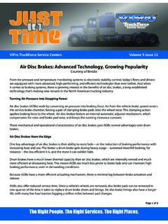
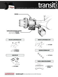
1 bendix Part NumberSerial Part Number Label Conventional RotorBendix Splined disc Rotor 103 Cable to Electrical Supply104 Cable Protection Plate101 Sensor101 Sensor105 Cable Guide(2 alternate designs used) Supply Port Return Spring PushrodLeverOuter brake PadInner brake PadRotor Eccentric Bearing Service brake ChamberBridgePressure PlateDiaphragm 19 Lever20 Eccentric Bearing 43 Bolt17 Bridge 27 Spring2 Carrier24 TurningDevice33 Wear Sensor22 InnerSeal16 Threaded Tube161 Tappet13 Tappet and Boot Assembly18/1 Spring brake or18/2 brake Chamber46 RotorPad Assembly 1212 Pad Assembly6 Guide Sleeve 2 Carrier4 Guide Pin9 Inner Boot58 Ring39 Caliper Bolt68 CapBushing1 Caliper5 Guide Pin13 Tappet and Boot Assembly23 Adjuster Unit26 Spring Clip27 Spring7 Brass Bushing9
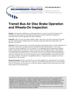
2 Inner Boot10 Cap12 PadAssembly16 Threaded Tube22 Inner Seal32 Chain Wheel161 Tappet Bushing61 Shear Adapter58 Ring45 Washer 40 Caliper Bolt 17 Bridge11 Pad Retainer30 Chain 44 Pad Retainer Pin37 Adjuster Cap 18/2 Service ActuatorActuatorHardware18/1 Spring BrakeActuator68 Cap39 Caliper Bolt6 Guide Sleeve 5 Guide Pin61 Shear Adapter1 Caliper13 Tappet and Boot Assembly26 Spring Clip11 Pad Retainer(Note: Pad Assemblyconsists of 12/1 plus 12/2)12/1 Pad12/2 Pad Holder Spring45 Washer 44 Pad Retainer Pin2 ABendixADB22X Carrier2 BBendix ADB22X-V Carrier7 Brass Bushing10 Cap161 Tappet Bushing40 Caliper Bolt 22 Inner Seal(Rotor Shield for Trailers)4 Guide Pin9 Inner Boot58 Ring *37 Adjuster Caps (2 styles supplied in kits)SD-1SD-2SD-3 Splined disc Rotor HardwareSD-1, -2, -3 Splined disc Rotor(SD) U-shaped RotorSteer HubDrive Hub U-shaped Rotor Fasteners(or Caliper Kit)
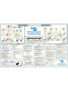
3 bendix ADB22X Anchor PlateCarrier MountingHardwareBendix ADB22X-V Anchor Plate37*Carrier MountingHardwareShieldKit(Drive or Steer)35 Double-Diaphragm-Style Spring brake ChamberFor bendix Air disc Brakes, as a vehicle travels forward, the wheel always rotates towards the fi xed-pin side of the caliper fi (longer pin)Floating pin A or B iscast hereType A Type B Wheel RotationWheel RotationOn most vehicles, Type A calipers are used on the passenger s side of the vehicle. (There are some rare driver s side applications.)On most vehicles, Type B calipers are used on the driver s side of the vehicle.
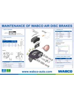
4 (There are some rare passenger s side applications.) Location of Wear Indicator Notches(Both sides of brake )Quick Visual Inspection of Pad Thickness and Rotor Notch in the caliper Notch in the carrierWhen the notches line up, it is time to schedule an inspection of the pads and rotor No notch in the carrierNotch in the caliperWhen the torque plate edge lines up with the notch, it is time to schedule an inspection of the pads and rotorTorque plate Push/PullBy Hand to Check the Caliper Movement Air disc brake InspectionFollow safe maintenance practices; chock wheels.
5 Engage spring brakes and cage spring. Release spring brakes and drain air from axle, spin the wheel by not due to air disc brake . See vehicle caliper/carrier assembly( )Drain air pressure from system. Restart test after caging spring brakesReplace caliper/carrier assembly( )NONONONONONONONOYESYESYESYESYESYESYESYE SR eplace guide pins ( ) OR replace caliper/carrier assembly ( )Replace components as needed with genuine bendix brake OKDoes the wheel turn smoothly?Is the spring brake fully/partially applied?Check running clearance ( ) - OK?Check caliper guidance ( ) - OK?
6 Check running clearance ( ) - OK?Check adjuster ( ) - OK?Check pad and rotor wear ( ) - OK?Check adjuster ( ) - OK? Component (Item / Condition)InvestigationSpecsProcedureWha t To ReplaceConsumable Items: These are considered to be normal wear items and should be repaired as part of regular preventive brake PadsAWornMeasure the thickness of the total pad (friction material and backing plate).Pads must be replaced when they reach in. (11 mm).Section the pads on both sides of the worn wear on single padMeasure the thickness of the total pad in at least two (2) places at top and two (2) places at bottom, at least 1/2 inch from the average difference of top vs.
7 Bottom, or left vs. right, should be no greater than in. (2 mm).Section the pads on both sides of the worn axle and replace the guide pins as wear on inboard vs. outboardMeasure the pad thickness as described for Item B, but also check guide pin wear and difference inboard to outboard should be no greater than in ( mm).Section damageInspect for minor chips near the edge and cracks on face (permitted) vs. major sections damaged or Figure 24 in the pads on both sides of the worn & SealsETears & cutsInspect the tappet and guide pin boots for cuts, cracks, and damage must be & the damaged boots and replace the resultant internal corroded guide pins as as Item E, but also check the running clearance before removing the brake damage must be Calipers Item LGuide PinsGBindingWith the pads removed, the caliper should move freely by hand.
8 Re-torque the carrier to torque plate bolts per the OE spec and procedure, if Figure 26 (slide) and Table 4 (torque) in & the worn guide pins as needed and replace the torque plate if the re-torque procedure does not resolve the playFeel for excessive play between the caliper and the Figure 27 in the worn guide pins as WornMeasure the rotor thickness with a long jaw must be greater than in. (37 mm).Section to the OEM recommendations for non- bendix rotors. For bendix rotors, replace the rotors on both sides of the damageMinor cracks and grooves are acceptable, but check for cracks over the outside Figure 25 in SD-23-7541 for surface to the OEM recommendations for non- bendix rotors.
9 For bendix rotors only, replace the rotor that is damaged. Non-Serviceable: These are non-serviceable items and pending warranty terms; these issues may be covered under not rotatingIf the 2nd sheer adapter breaks while turning the 10mm box-end wrench counterclockwise, the adjuster is must turn in both directions with a hand only must be replaced with malfunctioning too tight,dragging brakeWith the brakes released, check the running clearance between the tappet and the inboard gap should be between in. ( mm) and in. ( mm).Section PullCaliper Inboard Check the clearance at both tappets simultaneously: in.
10 To in.( mm. to mm.) Adjuster Cap Location 61 Adapter23 Adjuster37 CapTabTab37 Cap C ABMeasurement locations for BX276 brake pads. Do not measure on raised surfaces. Minor Damage - Is AcceptableWhere a small amount of brake material is chipped from the edge Major Damage - Is Not AcceptableSection damaged or missing 44 Pin26 Spring Clip45 Washer11 Pad Retainer Bar Rotor FrictionSurface Width f CaliperMovement1 Caliper5 Guide Pin9 Inner Boot9 Inner Boot7 Brass Bushing10 Cap6 Guide Sleeve4 Guide Pin39 Caliper BoltOutboardInboard68 Cap SHORT BEARING SIDELONGBEARING SIDE 12 Pad Assembly1 Carrier2 CaliperMagnetic Dial-Gauge MeasuresRange Here InspectBoot Extend LESS THAN in.