Transcription of X-Band Microwave Motion Sensor Module …
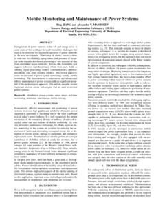
1 1of 7 MSAN-001X-Band Microwave Motion Sensor Module Application Note Introduction HB Series of Microwave Motion Sensor Module are X-Band Mono-static DRO Doppler transceiver front-end Module . These modules are designed for movement detection, like intruder alarms, occupancy modules and other innovative ideas. The Module consists of Dielectric Resonator Oscillator (DRO), Microwave mixer and patch antenna (see Diagram A). This Application Note highlights some important points when designing-in HB100 Module . Most of the points are also applicable to other models in this series. 2. Mounting Header Pins can be used to connected the terminals (+5V, IF, GND) to the amplifier circuit as well as mounting support. Other mounting methods may be used. Wave-solder the Module onto PCBA is possible but processes has to be evaluated to prevent deterioration.
2 No-cleaning process is recommended. Caution must be taken to avoid applying pressure or stresses to the chassis of the Module . As it may cause performance deterioration. Diagram A: Block Diagram 3. Before Power Up Connect the power supply, Ground and amplifier circuitry at the designed terminals. Designation of the connection terminals are printed on the PCB as shown in Diagram A. 2of 7 MSAN-001X-Band Microwave Motion Sensor Module Application Note 4. Power Supply The Module operates at +5 Vdc for Continious wave (CW) operation (see Annex 1). The Module can be powered by +5V low duty cycle pulsed trains in order to reduce its power consumption. Sample & Hold circuit at the IF output is required for pulse operation (see Annex 2).
3 5. Transmit Frequency The transmit frequency and power of the Module is set by factory. There is no user adjustable part in this device. The Module is a low power radio device (LPRD) or intended radiator. Local radio communication authority regulates use of such a device. Though user license may be exempted, type approval of equipment or other regulation compliance may be required. Annex 3 shown the allocated frequency in some countries. 6. Radiation Pattern The Module to be mounted with the antenna patches facing to the desired detection zone. The user may vary the orientation of the Module to get the best coverage. The radiation patterns of the antenna and their half power beam width (HPBW) are shown in below diagram. 0306090120150180210240270300330-30-24-24 -18-18-12-12-6-6 Azimuth0306090120150180210240270300330-3 6-30-30-24-24-18-18-12-12-6-6 Elevation 3of 7 MSAN-001X-Band Microwave Motion Sensor Module Application Note Output Signals Doppler shift - Doppler shift output from IF terminal when movement is detected.
4 The magnitude of the Doppler Shift is proportional to reflection of transmitted energy and is in the range of microvolts ( V). A high gain low frequency amplifier is usually connected to the IF terminal in order to amplify the Doppler shift to a processable level (see Annex 1). Frequency of Doppler shift is proportional to velocity of Motion . Typical human walking generates Doppler shift below 100 Hz. Doppler frequency can be calculated by Doppler equation in Annex 4. The Received Signal Strength (RSS) is the voltage measured of the Doppler shift at the IF output. The RSS figure specified in the technical data sheet is level of a 25 Hz Doppler shift, generate from the modulated Microwave signal received at the received antenna, The received Microwave signal is attenuated to 93 dB below the transmit Microwave signal from the transmit antenna of the same unit.
5 The 93dB loss is the total losses combining two ways free space loss ( dB for 30 meters at GHz), reflection less and absorption loss of the target, as well as other losses. This RSS figure can be view as an approximation of the output signal strength for a human at 15 meters away walking straight to the Module at km/hour. Reflection of a human body is varied with the size of the body, clothing, apparels and other environmental factors; RSS measured for two human bodies may vary by 50%. Circuit designer must take note the maximum and minimum Received Signal Strength (RSS) specified in technical data sheet, when designing the amplifier. Sensitive deviation between modules has to be considered when setting amplifier gain or alarm threshold. On-production-line gain adjustment may be necessary if a narrow window for triggering threshold is required.
6 Noise - The noise figure specified in the technical data sheet is the noise measured in an Anechoic chamber, that shield the unit-under-test from external interference, as well as reflection from surfaces. Hence, the figure is only presenting the noise generated by the internal circuit itself. Other than noises generate from internal electronic circuit, in actual applications , other noises may be picked up from surrounding, or other part of the electronic circuit. Specially attention has to be given to the interference pick up from fluorescent light, as the 100/120 Hz noise is closed to the Doppler frequency generated by human movement On and off switching of certain devices (relay, LED, motor, etc.) may generated high magnitude of transient noise at the IF terminal.
7 Careful PCB layout and time masking is necessary to prevent false triggering. 4of 7 MSAN-001X-Band Microwave Motion Sensor Module Application Note Level - DC level ( to Vdc) exists at the IF terminal and its polarity can be positive and negative. Its magnitude may vary over temperature. AC coupling is recommended for IF terminal connection. 8. Radiation Safety Microwave radiation from the Module is well below established safety standards for general public environment, like ANSI of USA and NRPB-G11 of United Kingdom. 9. Handling The Module has been fully tested to specifications. Upon opening, tighten or loosen the chassis will cause performance deterioration. The Module is an electrostatic sensitive device (ESD).
8 Precautions shall be observed for handling and assembly. 10. Product Support Please contact our product support engineers in the factory for technical assistance whenever necessary. Product Support ( Microwave Sensors) Tel: (65) 6568 7414 Fax: (65) 6567 6370 e-mail: 5of 7 MSAN-001X-Band Microwave Motion Sensor Module Application Note 1: Amplifier Circuit (CW operation) Annex 2: Amplifier Circuit (Pulse operation, PRF =2 KHz, Duty Cycle = 4%) This Capacitor is essential for FCC conformance when operate at Pulse mode 6of 7 MSAN-001X-Band Microwave Motion Sensor Module Application Note Annex 3: Allocated Frequency for Movement Detection Frequency Country Remark GHz Germany GHz France, Italy GHz USA, Belgium, Netherlands GHz UK Outdoor applications GHz UK Indoor applications Note: 1.
9 Though same frequency is allocated in some countries, national regulations may specify different EIRP, spurious emission or other requirements. 2. ETS 300 440 is the recommended harmonized standard for European Community, member country may adopt their own national regulation. 3. The regulations are subjected to change from time to time, please contact appropriate authorities for full and up-to-dated information. 4. Useful websites: Agency Website The Code of Federal Regulations, USA The European Radiocommunication Office The Radiocommunications Agency , UK 7of 7 MSAN-001X-Band Microwave Motion Sensor Module Application Note Annex 4: Doppler Equation Where Fd = Doppler frequency V = Velocity of the target Ft = Transmit frequency c = Speed of light (3 X 10⁸m/sec) = The angle between the target moving direction and the axis of the Module .
10 If a target is moving straight toward or away from HB100 (Ft = GHz) The formula is simplified to: Fd = (Velocity in km/hour) or (V in mile per hour) Conversion factor for other frequencies are shown as below: Frequency Fd (V in Km/hr) Fd (V in mph) GHz GHz GHz GHz GHz GHz CoscF2 VFtd =