Transcription of XC6206 - Your analog power IC and the best power ...
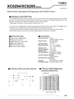
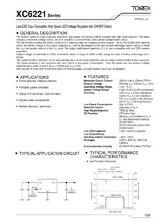
1 XC6206 Series ETR0305_008. GENERAL DESCRIPTION. The XC6206 series are highly precise, low power consumption, 3 terminal, positive voltage regulators manufactured using CMOS and laser trimming technologies. The series provides large currents with a significantly small dropout voltage. The XC6206 consists of a current limiter circuit , a driver transistor, a precision reference voltage and an error correction circuit . The series is compatible with low ESR ceramic capacitors. The current limiter's foldback circuit operates as a short circuit protection as well as the output current limiter for the output pin.
2 Output voltages are internally by laser trimming technologies. It is selectable in increments within a range of to SOT-23, SOT-89 and USP-6B packages are available. APPLICATIONS FEATURES. Smart phones / Mobile phones Maximum Output Current : 200mA ( type). Dropout Voltage : 250mV @ 100mA ( type). Portable game consoles Maximum Operating Voltage : Digital still cameras / Camcorders Output Voltage Range : ~ ( increments). Digital audio equipments Highly Accurate : 2%@VOUT Reference voltage sources Multi-function power supplies (+1% Low power Consumption : A (TYP.))
3 Low ESR Capacitor : Ceramic capacitor compatible Protection : Current Limit circuit Built-in Operating Ambient Temperature : -40 ~ +85 . Packages : SOT-23. SOT-89. USP-6B. Environmentally Friendly : EU RoHS Compliant, Pb Free TYPICAL APPLICATION circuit TYPICAL PERFORMANCE. CHARACTERISTICS. 1/15. XC6206 Series BLOCK DIAGRAM. *Diodes inside the circuit are an ESD protection diode and a parasitic diode. PRODUCT CLASSIFICATION. Ordering Information XC6206P - (*1). DESIGNATOR ITEM SYMBOL DESCRIPTION. Output Voltage 12~50 VOUT: =3, =0.
4 2 +2% (VOUT ), +30mV (VOUT< ). Accuracy 1 +1% (VOUT ). MR SOT-23 (3,000pcs/Reel). MR-G SOT-23 (3,000pcs/Reel). Packages PR SOT-89 (1,000pcs/Reel). - . (Order Unit) PR-G SOT-89 (1,000pcs/Reel). DR USP-6B (3,000pcs/Reel). DR-G USP-6B (3,000pcs/Reel). (*1). The -G suffix denotes Halogen and Antimony free as well as being fully EU RoHS compliant. 2/15. XC6206 . Series PIN CONFIGURATION. VIN. 3. VOUT 6 1 NC. NC 5 2 VSS. VIN 4 3 NC. 1 2. 1 2 3. VSS VOUT. VSS VIN VOUT. USP-6B SOT-23 SOT-89. (BOTTOM VIEW) (TOP VIEW) (TOP VIEW).
5 *The dissipation pad for the USP-6B package should be solder-plated in recommended mount pattern and metal masking so as to enhance mounting strength and heat release. If the pad needs to be connected to other pins, it should be connected to the pin number 4 (VIN). PIN ASSIGNMENT. PIN NUMBER. PIN NAME FUNCTIONS. SOT-23 SOT-89 USP-6B. 1 1 2 VSS Ground 3 2 4 VIN power Input 2 3 6 VOUT Output - - 1, 3, 5 NC No Connection ABSOLUTE MAXIMUM RATINGS. Ta=25OC. PARAMETER SYMBOL RATINGS UNITS. Input Voltage VIN + V. (*1).
6 Output Current IOUT 500 mA. Output Voltage VOUT ~ VIN + V. 250. SOT-23. 500(40mm x 40mm Standard board) (*2). 500. power Dissipation SOT-89 Pd mW. 1000(40mm x 40mm Standard board) (*2). 120. USP-6B. 1000(40mm x 40mm Standard board) (*2). Operating Ambient Temperature Topr - 40 ~ + 85 O. C. Storage Temperature Tstg - 55 ~ + 125 O. C. (*1) IOUT Pd / (VIN-VOUT). (*2) The power dissipation figure shown is PCB mounted and is for reference only. The mounting condition is please refer to PACKAGING INFORMATION. 3/15. XC6206 Series ELECTRICAL CHARACTERISTICS Ta=25OC.
7 PARAMETER SYMBOL CONDITIONS MIN. TYP. MAX. UNITS circuit . Output Voltage VOUT(T)< + IOUT=30mA. (Standard)(*2) VOUT(T) VOUT(E)(*3) VOUT(T)(*4) V . Output Voltage IOUT=30mA VOUT(T) (High Accuracy)(*2). Supply Current IDD - A . VOUT(T) , 1mA IOUT 50mA. Load Regulation VOUT - - E-1(*5) mV . VOUT(T)> , 1mA IOUT 100mA. Dropout Voltage 1 Vdif1(*6) IOUT=30mA - E-2(*5). VOUT(T) , IOUT=60mA mV . Dropout Voltage 2 Vdif2(*6) - E-3(*5). VOUT(T)> , IOUT=100mA. VOUT(T)< , VOUT(T)+ VIN , IOUT=30mA. VOUT/. Line Regulation - %/V.
8 ( VIN VOUT . VOUT(T) , VIN , IOUT=30mA. Maximum Output IOUTMAX VOUT VOUT(E) E-4(*5) - - mA . Current Short circuit ISHORT VOUT=VSS - E-5(*5) - mA . Current Input Voltage VIN - V . Output Voltage VOUT/. IOUT=30mA, Temperature ( Topr - 100 - ppm/ . -40 Topr 85 . Characteristics VOUT . *1: Unless otherwise stated, VIN = VOUT(T) + *2: (Standard): 2% ( VOUT(T)) , ( >VOUT(T)). (High Accuracy): 1% ( VOUT(T)). *3: VOUT(E) :Effective output voltage. *4: VOUT(T) :Nominal voltage *5: For E-1,E-2,E-3,E-4,E-5, Please refer to Electrical Characteristics Chart.))
9 *6: Vdif =VIN1 -VOUT1. VOUT1 :A voltage equal to 98% of the output voltage whenever an amply stabilized {VOUT(T) + } is input with each IOUT. VIN1 :The input voltage when VOUT1 appears as input voltage is gradually decreased. *7: The low ESR capacitors use that is more than F as CL is possible. 4/15. XC6206 . Series ELECTRICAL CHARACTERISTICS (Continued). Electrical Characteristics Chart E-1 E-2 E-3 E-4 E-5. MAX. NOMINAL LOAD DROPOUT DROPOUT SHORT. OUTPUT. VOLTAGE REGULATION VOLTAGE1 VOLTAGE2 CURRENT. CURRENT. VOUT (mV) Vdif1 (mV) Vdif2 (mV) IOUTMAX (mA) ISHORT (mA).
10 VOUT(T) MAX. TYP. MAX. TYP. MAX. MIN. TYP. 460 760. 700 960. 40 400 650 180. 60. 350 590. 580 860. 300 510. 250 450 155. 450 810. 45 200 410. 80. 150 390. 780. 130. 50 120. 350. 100 370. 710. 55 150. 60. 75 350 250 680 200. 100. 65. 70. 60 320 200 630. 250. 75. 80 50 290 175 600. 5/15. XC6206 Series TEST CIRCUITS. circuit . VIN VOUT OPEN. A. VSS. circuit . VIN VOUT A. 1 F 1 F. V (ceramic) VSS (ceramic). V. NOTES ON USE. 1. For temporary, transitional voltage drop or voltage rising phenomenon, the IC is liable to malfunction should the ratings be exceeded.