Transcription of XLPE Submarine Cable Systems Attachment to …
1 xlpe Submarine Cable SystemsAttachment to xlpe Land Cable Systems - User s GuideRev 52 xlpe Submarine Cable Systems | ABBC urrent rating for xlpe Submarine Cable Systems .. 3 Current rating for three-core cables .. 3 Current rating for single-core cables .. 4 Technical data for xlpe Submarine Cable Systems .. 5 Single-core cables with lead sheath .. 5 Three-core cables with copper wire screen .. 6 Three-core cables with lead sheath .. 7To make sure you have the latest version of this brochure, have a look at xlpe Submarine Cable SystemsCONTENTABB | xlpe Submarine Cable Systems 3 The xlpe Cable should at least have a conductor cross section adequate to meet the system requirements for power transmission capacity. The cost of energy losses can be redu-ced by using larger conductor.
2 Load losses in xlpe cables are primarily due to the ohmic losses in the conductor and the metallic screen. xlpe cables can be loaded continuously to a conductor temperature of 90 C. The dielectric losses of xlpe insulation are present also at no load. Those losses depend on the operation voltage applied and shall be considered above 100 losses in xlpe cables are lower than for EPR and fluid-filled current rating of Submarine cables follows the same rules as for land cables. However there are some differences: Three-core Submarine cables usually have steel wire ar-mour. Single-core cables have non-magnetic armour. Single-core cables can be laid separated or close. Close laying gives lower losses. Separation eliminates mutu-al heating but means higher losses in the armour.
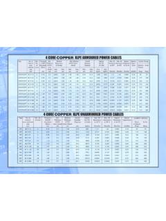
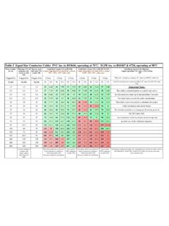
3 The induced current in the armour can be high, up to the same value as in the RATING FOR xlpe Submarine Cable SYSTEMSC urrent rating for three-core Submarine cables with steel wire armourContinuous current ratings for three-core Submarine cables are given in Tables 33-34 and for single-core cables in Tables 35-36. The continuous current ratings are calculated according to IEC 60287 series of standards and with the following condi-tions: One three-core Cable or one three-phase group of single-core cables Temperature in sea bed 20 C Laying depth in sea bed m Sea bed thermal resistivity K x m/WRating factors for sea bed temperature - see Tables 7-11 in the brochure xlpe Land Cable Systems - User s guide .Single-core Cable with lead sheath and wire armourThree-core Cable with optic fibers.
4 Lead sheath and wire armourTable 34100-300 kV xlpe 3-core cablesCrosssectionmm2 Copper conductorAluminium conductorAA30053043040059048550065554063 07156008007756601000825720 Table 3310-90 kV xlpe 3-core cablesCrosssectionmm2 Copper conductorAluminium conductorAA95300235120340265150375300185 4203352404803853005304304005904855006555 4063071560080077566010008257204 xlpe Submarine Cable Systems | ABBCURRENT RATING FOR xlpe Submarine Cable SYSTEMSC urrent rating for single-core Submarine cablesTable 35 Cross section Cu conductorRated voltage 10 - 90 kVWide spacingClose spacingmm2AA9541031512046535515052039518 5585435240670495300750545400840610500940 6706301050740800116080510001265870 Table 36 Cross section Cu conductorRated voltage 100 - 420 kVWide spacingClose spacingmm2AA1855804452406705053007505604 0084562050095069063010657608001180830100 01290895 Note 1: Calculations were performed assuming single layer of 5 mm copper armour wire.
5 Note 2: Aluminium cables (conductor made of aluminum and armouring made of aluminium alloy) will have a rating of 75 to 80 % for the same conductor area. Note 3: The rating data given in the above tables should be regarded as indicative only. Note 4: Cross sections larger than 1000 mm2 can be offered on request. ABB | xlpe Submarine Cable Systems 5 Single-core cables with lead sheathCross-sectionof con-ductorDiameterof con-ductorInsulationthicknessDiameterove r insulationLead sheath thicknessOuter diameter of cableCable weight (Aluminium) Cable weight (Copper)Capaci-tanceCharging current per phaseat 50 HzInductancemm2mmmmmmmmmmkg/mkg/m F/kmA/kmmH/kmTECHNICAL DATA FOR xlpe Submarine Cable SYSTEMST able 37 Single-core cables, nominal voltage 220 kV (Um = 245 kV) 38 Single-core cables, nominal voltage 275 kV (Um = 300 kV) 39 Single-core cables, nominal voltage 330 kV (Um = 362 kV) 40 Single-core cables, nominal voltage 400 kV (Um = 420 kV)
6 xlpe Submarine Cable Systems | ABBC ross-sectionof con-ductorDiameterof con-ductorInsulationthicknessDiameterove r insulationCross section of screenOuter diameter of cableCable weight (Aluminium) Cable weight (Copper)Capaci-tanceCharging current per phaseat 50 HzInductancemm2mmmmmmmm2mmkg/mkg/m F/kmA/kmmH/kmTECHNICAL DATA FOR xlpe Submarine Cable SYSTEMST able 41 Three-core cables, nominal voltage 10 kV (Um = 12 kV) 42 Three-core cables, nominal voltage 20 kV (Um = 24 kV) 43 Three-core cables, nominal voltage 30 kV (Um = 36 kV) cables with copper wire screenABB | xlpe Submarine Cable Systems 7 Cross-sectionof con-ductorDiameterof con-ductorInsulationthicknessDiameterove r insulationLead sheath thicknessOuter diameter of cableCable weight (Aluminium) Cable weight (Copper)Capaci-tanceCharging current per phaseat 50 HzInductancemm2mmmmmmmmmmkg/mkg/m F/kmA/kmmH/kmTECHNICAL DATA FOR xlpe Submarine Cable SYSTEMST able 44 Three-core cables, nominal voltage 45 kV (Um = 52 kV) 45 Three-core cables, nominal voltage 66 kV (Um = kV) 46 Three-core cables, nominal voltage 110 kV (Um = 123 kV) cables with lead sheath8 xlpe Submarine Cable Systems | ABBC ross-sectionof con-ductorDiameterof con-ductorInsulationthicknessDiameterove r insulationLead sheath thicknessOuter diameter of cableCable weight (Aluminium) Cable weight (Copper)
7 Capaci-tanceCharging current per phaseat 50 HzInductancemm2mmmmmmmmmmkg/mkg/m F/kmA/kmmH/kmTECHNICAL DATA FOR xlpe Submarine Cable SYSTEMST able 47 Three-core cables, nominal voltage 132 kV (Um = 145 kV) 48 Three-core cables, nominal voltage 150 kV (Um = 170 kV) 49 Three-core cables, nominal voltage 220 kV (Um = 245 kV) 50 Three-core cables, nominal voltage 275 kV (Um = 300 kV) cables with lead sheathABB | xlpe Submarine Cable Systems 9 Notes10 xlpe Submarine Cable Systems | ABBN otesContact us2010-04, 2GM 5007 -sub GB rev5 ABB s high voltage Cable unit in SwedenPhone: +46 455 556 00 Fax: +46 455 556 55 E-Mail.