Transcription of XMTG818 Digital Temperature Controller - fctcl.com
1 OPERATION MANUAL. FOR. MICROCOMPUTER BASED. Digital Temperature Controller . XMTG 808 ,XMTG 818. (2008 version). -1- Preface Thank you for the purchase of our microcomputer based Digital Temperature controllers XMTG-808,XMTG-818. This kind of products has received CE approval. The manual contains instructions about assemblages, functions, operations and cautions on using the XMTG-808,XMTG-818. Caution To avoid the misuse of this Controller , please ensure to read this manual and confirm the model carefully before using the apparatus. The instrument should be used according to the coach described in the manual ,otherwise, it may conk out or cause fire. Be sure to follow the warnings, cautions and notices. If not, it could cause serious injury or malfunction. Specifications of the XMTG-808,XMTG-818 and the contents of this instruction manual can be modified without any notice.
2 Care has been taken to assure that the manual match with your instrument, if not ,or there are any doubts, mistakes or questions about it, please inform our sales department timely. The instrument is designed to be installed in a control panel. If not, tests must be taken to ensure that the operator cannot touch power terminals or other high voltage sections. Any unauthorized transfer or copying of this document in part or whole are prohibited. Safety Precautions Be sure to read these precautions before using our products. The safety precautions are classified into categories: "Warning" and "Caution". Depending on circumstances, procedures marked on Caution may lead to serious results, so be sure to follow the directions for usage. Warning The sign means dangerous conditions that may cause death or serious injury because of not being carried out properly. Caution The sign means dangerous conditions that may cause superficial/medium injury or physical damage.
3 And it also can degrade or damage the Controller . 1. Installation precautions Caution This Controller should be used under the following environmental conditions: Install the Controller in the place as below: -2- Lack of dust and corrosive gas No flammable, explosive gas. No mechanical vibration and shocks. No exposure to direct sunlight and an ambient Temperature between 0 to 50 (32to 122 ). that does not change suddenly. An ambient non-condensing humidity between 35%RH and 85%RH. Little of electromagnetic interference. Avoid direct contact with water, oil or chemicals and the vapors of these substance Note: Do not install the Controller near flammable material even though the shell of the Controller is flameproof. Avoid setting this Controller directly with flammable material. 2. Wiring precautions Caution Use solderless terminal with insulation sleeve to connect the M3 screw pole of the rear of the Controller as per the connection label affixed to the shell.
4 Tighten the terminal screw within the suitable torque. If excessive force is applied to the screw, the screw or shell be damaged Please apply appropriate power source to the sensor according to sensor rated power. Do not apply the commercial power source to the sensor which is connected to the input terminal, otherwise , input circuit may cause short circuit or burnt out. This Controller has no built-in power switch, circuit breaker or fuse. It is necessary to install them near the Controller . Recommended fuse installation: Time-lag fuse, rated voltage 250 VAC, current 2A. When using 24V AC/DC for the power source, do not confuse the polarity when it is DC. 3. Running and maintenance precautions Caution The Controller adopt artificial intelligence control, which is a new algorithm using fuzzy logical PID auto-tuning . Do not touch the terminals when the Controller is working.
5 It may cause electric shock or problems in operation. Be sure to turn the power source switch state to OFF when adjusting and touching the terminal ,if not it maybe result in electric shock and cause severe injury and death. Clean Controller only with soft, dry cloth. Do not strike or scratch it with a hard object or press hard on them. -3- ----CONTENTS----- 1. Main specification--------------------------- ---------------------------------------- -------4. Specification--------------------------- ---------------------------------------- -----------------------4. Product confirmation---------------------------- ---------------------------------------- -----------4. Name and functions of the sections-------------------------------- ------------------------------4. 2. Display status---------------------------------- ---------------------------------------- --------------------5.
6 Operation description----------------------------- ---------------------------------------- ---5. transfer-------------------------------- ---------------------------------------- --------5. setup----------------------------------- ---------------------------------------- ------------5. mode switch---------------------------------- --------------------------------------6. parameters------------------------------ ---------------------------------------- -------6. Artificial intelligence control and auto tuning---------------------------------- ----------------6. 3. Wiring connection------------------------------ ---------------------------------------- ------------------6. 4. Setup flow chart----------------------------------- ---------------------------------------- ---------------7. Alarm parameter ALM1 , ALM2 , Hy-1 , Hy-2 -------------------------------------9. Dead band parameter Hy ---------------------------------------- ------------------------------9.
7 Control mode parameter At ---------------------------------------- ---------------------------9. Control action explanations---------------------------- ---------------------------------------- -10. P , I , D .--------------------------------------- ---------------------------------------1 0. PID auto-tuning of this Controller ------------------------------ -----------------------10. Auto-reset (offset correction) ---------------------------------------- -------------------11. Control period T ---------------------------------------- --------------------------------------11 . Input specification parameter Sn ---------------------------------------- -------------------12. Decimal point setting parameter dp ---------------------------------------- ----------------12. P-SL and P-SH :scale definition parameter for linear input/retransmission output---------------------------------- ---------------------------------------- ---------------------12.
8 Input shift parameter Pb ---------------------------------------- ------------------------------12. Output definition parameter OP-A , outL , outH ----------------------------------13. Alarm output definition parameter AL-P ---------------------------------------- --------13. Function parameter COOL ---------------------------------------- -------------------------13. Communication interface related parameters Addr and bAud ------------------13. Input Digital filter parameter FILT ---------------------------------------- ---------------14. Operation condition parameter A-M ---------------------------------------- ---------14. Privilege for parameter setting Lock ---------------------------------------- -------------14. Field parameter definition EP1-EP8 ---------------------------------------- --------------14. 5. Additional remarks of time proportional output---------------------------------- ---------------15.
9 6. Further description about general work mode------------------------------------ ---------------15. ON-OFF control instrument (simple Temperature Controller ) --------------------------15. 3-point (high, low alarm) control instrument------------------------------ -----------------15. -4- 1. Main specification: Specification: Input signal and Temperature range(six input signal are for selection in a Controller ): Thermocouple: S (-50- +1700C), K (-50 - +1300C) , E (0 - +800C), J (0 -1000C). Thermo resistance: Pt100 (-200-+600C) Cu50 (-50-+150C). Precision: 1B. Response time: s (filter parameter sets 0). Adjusting mode: a. 2-bit (HY adjust) b. artificial intelligence PID control Output: Relay 250V/3A or 30 VDC/10A(impedance). Alarm function: top-limit, bottom-limit, top error and bottom error for selection Alarm output: relay contact AC250V 3A(impedance). Insulate resistance voltage: power-relay-signal 2000V signal-signal 600V.
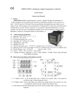
10 Manual function: auto/manual bi-directional non-reference switching. Power supply: 85-242 VAC, 50/60Hz. power consumption 4W. Work environment: Temperature 0-50 . Humidity <85%RH. No corrode and strong electromagnetism disturb The Controller has received CE approval. Product confirmation: Product type code: XMT 8 8 . (1) (2) (3) (4) (5). Meaning of the code: (1) Panel dimension< width height (mm)>: G: 48 48. (2) 8 Control Mode: four key set, two display, PID control (3) Alarm output : 0 : no alarm, 1 : one alarm(ALM1). 3 : two alarm (ALM1 and ALM2). (4) 8 Signal input Type: 6 selected input type (5) Control output: z Nothing : Relay contact z A : Single-phase over-zero spark pulse z C : 4-20mA. z G : 2-bit SSR. z K : With communication module (RS485). (Note: The output A , C , G and K require special order). Name and function of the section: (1) PV display: Indicate the process variable (PV) with the red LED.