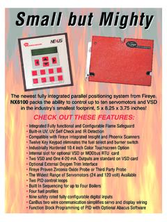
Transcription of YB110/YB230 FIREYE BurnerLogiX
1 1 DESCRIPTIONThe FIREYE BurnerLogiX System is a microprocessor based burner management control systemdesigned to provide the proper burner sequencing, ignition and flame monitoring protection on auto-matically ignited oil, gas, and combination fuel burners. In conjunction with limit and operating con-trols, it programs the burner/blower motor, ignition and fuel valves to provide for proper and safeburner operation. Through SMART LED S, the control provides current operating status and lockoutinformation in the event of a safety shutdown. Optional VFD and LCD displays are available thatmay be either plugged in or mounted remotely to give full language descriptors of current status anddiagnostic lockout information. Refer to BurnerLogiX PROGRAMMER SELECTION later in thisdocument for the various combinations of programmer and display complete BurnerLogiX system includes the YB110 (YB230) chassis equipped with the type offlame amplifier required for the application, appropriate flame detector, plug-in programmer mod-ule, wiring base and optional alpha-numeric display.
2 Interchangeable programmer modules allow forcomplete versatility in selection of function, timing and flame failure response optional alpha-numeric display has 2 lines by 16 characters per line. It is available in either vac-uum fluorescent or liquid crystal formats. The advantage of VFD is high brightness and extendedtemperature range down to 40 F. Both displays contain a fully functional keypad. You can easilyscroll through the various menus to view the current operating status, review programmer configura-tion, and lockout history. When mounted remotely, the displays provide NEMA 4x(IP66) advantage of the BurnerLogiX control family is the ability to set many of the operating parame-ters associated with proper and reliable burner operation allowing inventory of various programmertypes to be kept to a YB110 (YB230) is a chassis/ flame amplifier module complete with mounting screws and blankdisplay module.
3 The display module (BLV512 (vfd) or BLL510 (lcd)), if required, must be orderedseparately. Interchangeable YP programmer modules allow for complete versatility in selection ofcontrol function, timing, and flame scanning means. Functions such as pre-purge time, recycling ornon-recycling interlocks, high fire proving interlock, and trial for ignition timing of the pilot andmain flame are determined by the programmer module. The BurnerLogiX system can be used withultra-violet, auto-check infrared, flame rod, self-check ultra-violet flame scanners or direct coupledintegrated scanners by choosing the proper chassis/ flame amplifier FIREYE BurnerLogiX MICROPROCESSOR-BASEDINTEGRATED BURNERMANAGEMENT CONTROLBL-1001 August 7, 2018 APPROVED2 Wiring bases for the BurnerLogiX control are available pre-wired with 4 foot ( ) lead wires colorcoded and marked for easy installation or with an integral terminal block capable of a accepting up to2 X 14 AWG wires.
4 The wiring base terminal block is available with knockouts for conduit or openended for cabinet mounting. The pigtail wiring base is 4" X 5" ( x 127mm) and the terminalblock wiring base is 4" X 7" ( x ). Additional functions of the BurnerLogiX system include: A non-volatile memory allows the control to remember its history and present position evenwhen power is interrupted. A consistent flame signal read-out via display module or 4-20 mA output. Read-out of main fuel operational hours and complete cycles via display module. Modbus communications via RS485 multi-drop link. Proof of fuel valve closure during the off cycle. Burn-in time of program parameters occurs after 8 hours of main valve on time. A run/check switch allows the operator to stop the program sequence in any of fourdifferent positions (Purge, PTFI, MTFI or Auto).
5 Remote Display mounting with NEMA 4 protection. Remote Reset. Programmable communication baud rate allows for DCS compatibility. Keypad selectable language readout. Revert to pilot can increase burner turn down. Additional terminals provided for applications requiring additional inputs and : While programmers are mechanically interchangeable in that they mate with acommon chassis/amplifier module, you must select the correct model for your application of a control can result in an unsafe condition hazardous to lifeand property. Selection of a control for a particular application must be made by a compe-tent professional, such as a boiler/burner service technician licensed by a state or other gov-ernment agency. NOTICE: This equipment generates and can radiate radio frequency energy, and if notinstalled and used in accordance with the instruction manual may cause interference toradio communications.
6 It has been tested and found to comply with the limits for a Class Acomputing device pursuant to Subpart J of part 15 of FCC Rules, which are designed toprovide reasonable protection against such interference when operated in a commercialenvironment. Operation of this equipment in a residential area may cause interference inwhich case the user, at his own expense, will be required to take whatever measures whichmay be required to correct the TABLE OF CONTENTSBURNERLOGIX SPECIFICATIONS ..5 PART NUMBERS AND APPROVALS ..8 ORDERING INFORMATION ..9 INSTALLATION PROCEDURE ..13 WIRING BASE .. 13 PTFI*MTFI TIMINGS .. 17 LED INDICATOR LIGHTS .. 18 REPLACEABLE FUSE .. 19 DESCRIPTION OF FUNCTIONS OF OPERATING CONTROLS ..20 SETTING PROGRAMMER PARAMETERS ..20 KEYPAD DESCRIPTION .. 21 PROGRAM SET UP SUB-MENU.
7 22TO VIEW AND MODIFY A PROGRAMMABLE PARAMETER .. 23 flame SCANNERS ..24 INSTALLATION - UV SCANNERS .. 24 OPERATION 45UV5 & 55UV5 SELF-CHECKING UV SCANNER .. 25 WIRING - UV SCANNERS .. 26 INSTALLATION INFRARED SCANNER TYPE 48PT2 .. 26 OPERATION - IR LEARN .. 27 INSTALLATION - 69ND1 flame ROD .. 29 INSTALLATION - 85 SERIES PHOENIX SCANNER.. 30 INSTALLATION - 95 SERIES INSIGHT SCANNERS .. 32 SYSTEM INFO SUB-MENU ..35 SYSTEM OPERATION ..35YP100 OPERATING SEQUENCE.. 36 START-UP (NORMAL CYCLE) .. 37YP200 OPERATING SEQUENCE.. 39YP300 OPERATING SEQUENCE.. 40YP138 PROGRAMMER .. 42 LOCKOUTS ..46 SAFETY SHUTDOWN .. 46 DIAGNOSTIC MESSAGES.. 47 RESETTING THE CONTROL.. 47 LOCKOUT CODES .. 48 LOCKOUT HISTORY SUB-MENU .. 49 COMMUNICATIONS..50 MESSAGE FORMAT .. 50 MODBUS MESSAGE TABLE.. 51 INPUTS .. 52 OUTPUTS .. 52 EXPLANATION OF LOGSTAT.
8 54 BurnerLogiX MESSAGES .. 55 INTERLOCK ANNUNCIATOR.. 57 OPERATIONAL FEATURES ..584-20 mA TEST JACKS .. 58 CHECK-RUN SWITCH .. 59 OPERATIONAL TEST ..60 TEST CHECKOUT PROCEDURES .. 60 SUGGESTED GROUNDING RULES.. 62 MAINTENANCE .. 634 Table of FiguresFIGURE ORDERING INFORMATION .. 12 FIGURE BASE DETAILS.. 13 FIGURE PROGRAMMER .. 15 FIGURE DESCRIPTION .. 21 FIGURE MENU STRUCTURE .. 21 FIGURE MENU.. 22 FIGURE SCANNERS.. 24 FIGURE YOUR SCANNER ..24 FIGURE SCANNER INSTALLATIONS .. 25 FIGURE SELF CHECK SCANNER OPERATION .. 26 FIGURE INSTALLATION .. 27 FIGURE WIRING DIAGRAM .. 30 FIGURE TYB110DC/YB230DC WITH 85 UVF4-1 QDWR SCANNER .. 31 FIGURE WIRING DIAGRAM .. 33 FIGURE BurnerLogiX & INSIGHT I .. 34 FIGURE INFO SUB-MENU .. 35 FIGURE OPERATING SEQUENCE .. 36 FIGURE OPERATING SEQUENCE .. 39 FIGURE OPERATING SEQUENCE.
9 40 FIGURE WIRING DIAGRAM .. 41 FIGURE WIRING DIAGRAM .. 42 FIGURE WIRING DIAGRAM .. 43 FIGURE HISTORY .. 49 FIGURE VIEW COMMS .. 50 FIGURE WIRING FOR YZ300 INTERLOCK ANNUNCIATOR .. 53 FIGURE VIEW 4-20 mA JACKS .. 58 FIGURE JACKS (4-20 mA) VS. flame STRENGTH .. 58 FIGURE RUN SWITHCH .. 59 FIGURE flame TEST .. 62 Table of TablesTable 1:OPERATING TEMPERATURE LIMITS ..5 Table 2:LOAD RATINGS .. 6 Table 3:AGENCY APPROVALS ..8 Table 4:APPLICABLE BULLETINS ..9 Table 5:ORDERING INFORMATION..9 Table 6:PROGRAMMER MODULES ..9 Table 7: BurnerLogiX DISPLAYS ..10 Table 8: BurnerLogiX WIRING BASES ..10 Table 9: BurnerLogiX ACCESSORIES ..10 Table 10:SCANNER SELECTION..10 Table 11:PRE-WIRED WIRING BASE, P/N 60-2810-1 (shown for 120 VAC) ..13 Table 12: BurnerLogiX PROGRAMMER SELECTION ..16 Table 13:PTFI & MTFI TIMING ..18 Table 14:LED INDICATORS.
10 18 Table 15:MODIFIABLE PARAMETERS LOCATED IN PROGRAM SETUP MENU ..23 Table 16:PHOENIX SCANNER CABLE COLOR CODE ..31 Table 17:DIAGNOSTIC MESSAGES ..47 Table 18:LED CODES ..48 Table 19:MESSAGE FORMAT ..50 Table 20:MODBUS ..50 Table 21:MODBUS MESSAGE TABLE ..51 Table 22:INPUTS AND OUTPUTS ..52 Table 23:YZ300..53 Table 24:LOGSTAT..54 Table 25: BurnerLogiX MESSAGES ..55 Table 26:DIAGNOSTIC MESSAGES ..56 Table 27:ANNUNCIATOR MESSAGES ..575 .. BurnerLogiX SPECIFICATIONSS upply Voltage:YB110120 VAC (+10%, -15%) 50/60 HzYB230230 VAC (+10%, -15%) 50/60 HzPower Consumption: 25 VATemperature Rating:-40 C (-40 F) to +60 C (140 F)Protection Category:YB110 (YB230) control NEMA 1 (IP01)Display, remote mounted NEMA 4X (IP66)Unit Dimensions:Wiring base 60-2810-1 - " (101 mm) W x " (127mm) HWiring base 60-2812-1, 60-2814-1 - " (101 mm) W x " (178 mm) HShipping Weight:YB110 (YB230) Approx.