Transcription of Your Steering Column Specialist - Disc Brake, Steering and ...
1 Basic Installation Instructions for: ididit s Universal Tilt Columnsididit inc. 610 S. Maumee St. Tecumseh, MI 49286PH: 517-424-0577 FAX: 3/19/2010 Instruction # 8000000020 What s inside this installation booklet:U-Joint & Shafting Installation Lever Installation Wiring your Column Synchronizing your Column Additional Notes Accessory & Add-On Checklist ididit Steering Column Specialist1120120010, 1120160010, 1120280010, 1120300010, 1120320010, 11203500101520120010, 1520160010, 1520280010, 1520300010, 1520320010, 15203500101120120020, 1120160020, 1120280020, 1120300020, 1120320020, 11203500201520120020, 1520160020, 1520280020, 1520300020, 1520320020, 15203500201120120051, 1120160051, 1120280051, 1120300051, 1120320051, 11203500511520120051, 1520160051, 1520280051, 1520300051, 1520320051, 15203500511030120030, 1030160030, 1030280030, 1030300030, 1030320030, 10303500301030120040, 1030160040, 1030280040, 1030300040, 1030320040.
2 1030350040 For # sWe will first give you an overview of mounting the Steering Column in the most common street rod or hot rod applications. The Steering Column must be supported at the dash and where it protrudes through the firewall. It is impor-tant that the Steering Column is tight and secure. There is a shorty application which will use two drops under the dash, with the support bearing through the firewall (since the Column ends under the dash). To attach your Column to the Steering gear box, a u-joint is attached to the Column , a shaft is attached to the u-joint, and that shaft will lead down to a u-joint con-nected to the gear box (or rack).It is highly recommended that you test fit your Steering Column before painting the Column . Test fitting now will save you a head-ache later on. We are not responsible for Installation:For proper installation of u-joints and couplers on your Column , follow manu-facturers recommendations, but in general, two basic styles used on your ididit, inc.
3 Steering Column :DD Output Shaft (our most common shaft):Double D output shafts are either 1 or 3/4 diameter. Most u-joint manufacturers use two setscrews to fasten the u-joint to a DD shaft. These two set screws are positioned 90 degrees from each other. To install a u-joint over the shaft simply slide the u-joint over shaft until it is fully engaged in the joint (Borgeson Universal recommends 7/8 1 engagement). Use a marker to make a mark through each hole in the joint. Remove the joint. Using a quarter inch drill bit, spot the shaft where the setscrews will seat. Re-install the joint and install setscrews and jam nuts. (Note: all joint mfg s recom-mend using a thread-locking compound on setscrew and nut).Spline Output Shaft:Spline output shafts are either 1 48 or 3/4 36. To install your u-joint simply slide the u-joint over the spline, taking care to line one set screw up with the flat spot on the shaft.
4 If the shaft has no flat spot, slide the joint on so the shaft is fully engaged in the joint (Borgeson Universal recommends 7/8 1 en-gagement). Use a marker to make a mark through hole in the joint. Remove the joint. Using a quarter inch drill bit, spot the shaft where the setscrew will seat. Re-install the joint and install setscrew and jam nut. (Note: all joint manufacturers recommend using a thread-locking compound on setscrew and nut).1 Thank you for purchasing an ididit Steering Column !How to install your Tilt, Turn Signal Levers and Hazard KnobTurn Signal Lever:The signal lever is the lever closest to the top of the Column . With the Steering wheel and adaptor removed, look down from the top of the Column and you ll see where a single screw holds the signal lever in place. Insert the new lever using the provided screw into round hole (not D shaped hole).
5 When installing this lever in a new Column , use the screw supplied to fasten the lever in the recessed area on the signal switch Lever:Look directly below the turn signal lever, and you ll see another opening in the Column . Inside this opening is a threaded hole which the new lever screws Flasher Knob:Almost directly opposite the turn lever on the steer-ing Column is another opening. Inside this open-ing is a hole in the nylon switch. Simply screw the new knob in place (clockwise). When completing installation of flasher knob make sure that the knob is in the out (off), position so when finished wiring you don t have any Column Shift Application:Place Column shift knob onto the shift lever. Once your lever is on, use setscrew (provided) and adjust knob so set screw is not facing for-ward, tighten setscrew.
6 Do not remove the up-per shift lever for any reason! The tension spring will pop out and it is very difficult to your ColumnThis ididit Steering Column uses a standard 3 7/8-inch male connect. How-ever, some GM columns use a 4 -inch male connector. Connectors do not interchange and must be used in pairs. A mate to the 3 7/8 inch plug is available through ididit. If you need to change this connector for any reason the following schematic will be Button Wiring:A horn may require two wires to properly func-tion with an ididit Column . The center lug on the button should connect to a horn wire, which is provided by ididit with your Steering Column . This horn wire will slide into the horn cam (white plastic tube sticking up on the top of the Column ). If there is a second wire off to the side it is prob-ably a ground wire (check with the horn button manufacturer to be sure).
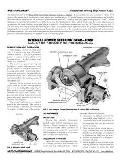
7 This is normally used when an o-ring is used to hold the button in place. The o-ring does not provide sufficient ground, therefore, an additional wire is provided to ground the horn button. If there is not a hole in adaptor to ground to, use one of the puller holes with a short bolt to attach the wire to the your ColumnIn order to insure proper functioning, this Steering Column must be in-stalled in sync with the rest of the Steering system. Turn signal cancellation and wheel position, as well as smooth Steering operation depends on it. Although not all of them may need adjustment, the complete table of steps required for full synchronization is as follows (continued on next page):3 The front wheels must be pointing straight forward with the Steering 1. toe set reasonably the input shaft of the gearbox or rack from lock to lock and set 2.
8 The box exactly half way between. For example, if the shaft rotates three full turns from lock to lock. The center will be at 1 turns from either locked the Steering arm and drag link, and adjust tie rod ends to get the 3. drag link to fit without moving either the box/rack or the front wheels. Rotating each tie rod end the same number of turns will preserve the Column mounted in posi-4. tion and two joints are used on a shaft, the forks of the yokes clos-est to each other should be in line, or in phase . Premature wear or binding can result if the u-joints are not phased properly. Some-times if the u-joints are at a severe angle, even if they are phased cor-rectly, a hard spot in the Steering may occur for no apparent reason. If this happens, index the u-joints two or three splines in one direction.
9 The hard spot should disappear or be the shaft or joint on the gear box/rack. Leave the upper part of 5. the shaft unconnected for the time the Column housing so that the signal switch arm is level to 6. the left hand the Column through firewall, into your To achieve proper synchronizing of your Column the finished instal-8. lation of your Column should look like the col-umn diagram below. If post on horn cam is not at 10:30, grasp post and turn it until it is at 10:30. Once completed, your Column now is in !! Steering Wheels:The top shaft of the Column is the same as a GM passenger car from 1969-94 (Van columns & some truck columns are not the same as pas-senger cars). Original wheels from these years will bolt directly to the top of the Column with no modifications. An aftermarket wheel will require an adaptor.
10 Align the spline and horn cam on the top of the Column with those in the adaptor and slide it onto the Column . A nut has been provided with your Steering Column . The nut will secure the wheel to the top of the Column . The nut on the wheel should be torqued to 40 ft Shift Linkage Installation:At the bottom of your Column you will notice a lever. This is the shift lever where your linkage will attach from the Column to the transmis-sion. Note the 5/16 hole through the bushings, most kits use a 5/16 bolt to secure the rod to the Column . Please follow the kit instructions for the linkage, but make sure that no part of their kit hits the metal portion of the lever, as it will create a rattle in the CAN T GET IT?ididit inc. has been serving the rodding community for over 20 years and one of the major factors has always been our excellent customer service.