Example: tourism industry
Z-100 Automatic Antenna Tuner - LDG Electronics
(e.g., ladder line), an external balun is required. The LDG RBA-1:1 balun will work with short random wires and the RBA-1 4:1 balun is suited for longer wires. Connect the HF antenna jack on your transmitter or transceiver to the Transmitter jack on the back of your Z-100 tuner using a coax jumper with standard PL-259 plugs.
Tags:
Information
Domain:
Source:
Link to this page:
Documents from same domain
LDG AT-1000ProII 1000W Automatic Antenna Tuner
ldgelectronics.comConnect your antenna’s 50-ohm coax feedline to the ANT 1 jack on the rear of the AT-1000ProII. ... If use with longwires or ladder-line-fed antennas is desired, an external balun rated to 1000 watts is required. ... the 1/8” stereo plug on the other end of the ICOM interface cable to the jack marked Radio on

LDG AT-100Pro 100W Automatic Antenna Tuner
ldgelectronics.comthe supplied coax jumper cable, or a similar 50 ohm coax cable rated 125 watts or higher. Connect a 50-ohm antenna feedline coax to the ANT 1 jack on the back of the AT-100Plus, and optionally connect a second antenna feedline to the ANT 2 jack. The AT-100Pro is designed to interface directly with many popular ICOM and Yaesu transceivers,

LDG AT-200ProII 200W Automatic Antenna Tuner
ldgelectronics.comautomatic tuners and related products for every amateur need. Congratulations on selecting the LDG Electronics AT-200ProII 200-watt automatic tuner. The AT-200ProII provides fully- and semi-automatic antenna tuning across the entire HF spectrum plus 6 meters, at power levels up to 250 watts (100W on 6m).
LDG AT-600ProII 600W Automatic Antenna Tuner
ldgelectronics.comLDG pioneered the automatic, wide-range switched-L tuner in 1995. From its laboratories in St. Leonard, Maryland, LDG continues to define the state of the art in this field with innovative automatic tuners and related products for every amateur need. Congratulations on selecting the LDG Electronics AT-600ProII 600 watt automatic tuner.

LDG IT-100 100-Watt Automatic Tuner for Icom Transceivers
ldgelectronics.comConnect the other end of the supplied radio interface cable to the “Radio” jack on the back of the IT-100. Turn on the radio. Select the desired operating frequency and mode. Push and hold the TUNER/CALL button on the front of the radio for one second (until the Tuning LED comes on), then release. The transceiver automatically keys up with ...

LDG Z-100Plus 100-Watt Automatic Tuner
ldgelectronics.comThe power and radio plugs then connect to the tuner. The tuning process can start by either pressing the tune button on the tuner or the radio. For Yaesu FT-897 and 857, use the optional Y-ACC cable and plug the red end marked “Radio” into the radio’s ACC port.
Related documents
The G5RV Antenna System -- An Analysis
www.bvarc.orgTo Balun, or not to Balun…. (that is the question) •Varney initially recommended using a Balun –In 1984 he retracted that after doing further measurements. •He found / read with highly reactive Z’s: –SWR above 2:1 the losses increase and cores will saturate – losing RF power to heat. •Design Note: only use core based baluns in matched
Connecting Your Receiver to the Antenna - DXing.com
www.dxing.comIn Fig. 5A, the receiver has only two antenna terminals, one for the antenna (A1) and the other for the ground or earth (G). If a single wire downlead is used, then it is connected directly to the A1 terminal. Either scrapping the end, or use of a spade lug, as ... BALUN transformer, with either 1:1 or 4:1 impedance transformation (depending on ...
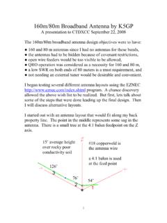
160m/80m Broadband Antenna by K5GP
www.ctdxcc.orgFor the antenna layout below, the center capacitor is 15 pF at element 3 between elements 2 and 4 and a 4:1 balun feeds the antenna between elements 1 and 2. The SWR is less than 1.7 to 1 across the entire 80 meter band. How do we get back the 160 meter resonance? By placing a series L and C across the 15 pF capacitor. When we do this, we must
LDG AT-1000ProII 1000W Automatic Antenna Tuner
ldgelectronics.com•Tunes 6 to 1,000 ohm loads (16 to 150 on 6m), 6 to 4,000 ohms with optional 4:1 balun. •LED bargraph displays power level, SWR, and status. •Antenna Indicator LED shows the currently selected antenna. • Bypass LED shows when tuner is in pass-thru. • User-selectable operating parameters: Auto/Semi, 1kW/100W watt scale, and more.

The Delta Loop Antenna….
www.norfolkamateurradio.orgWhen cutting wire to make the Antenna, always add some for final tuning and the physical attachment on insulators. What do you need? ... , Improvised or make your own • Coax Feeder – Coax 50 and or 75 ohm • Slotted line –450 (you will need a balun and ATU to match to your TX for multiband use) Delta Loop Feed point. RG58 Cable ...

0A-ESP8266 Datasheet EN v4.3
components101.comESP8266EX is among the most integrated WiFi chip in the industry; it integrates the antenna switches, RF balun, power amplifier, low noise receive amplifier, filters, power management modules, it requires minimal external circuitry, and the entire solution, including front-end module, is designed to occupy minimal PCB area.

BALUN 9:1 per antenna Long-Wire - radioamatoripeligni.it
www.radioamatoripeligni.itBALUN 9:1 per antenna Long-Wire Ivo Brugnera brugneraivo@alice.it Ciao a tutti, nuovo anno nuovi articoli semplici, facili e funzionali. Questa volta parliamo di antenne HF, antenne facilissime da costruire e di sicuro funzionamento, praticamente si tratta di adattare antenne WIRE di lunghezza casuale, dettata dallo
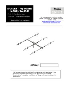
MOSLEY Trap Master Version MODEL TA-33-M 2011
www.radiomanual.infoChoose the installation site of the antenna carefully. Determine the overall height of the complete antenna system; include the supporting structure’s height (tower, slip-up mast, etc.), rotor (if needed) and the length of the antenna’s longest element. The antenna system should be installed a minimum of ten feet over and above the collective

Baluns & Common Mode Chokes
www.na0tc.orgNo Balun 4. Source moved up to antenna feed point 5. Transmission line replaced with a wire. Example of Tripole Common Mode Current: Tom Thompson (W0IVJ) •40 M halfwave Dipole with halfwave wire for feed line •No Balun •Tx power = 1500 W •Feedline NOT grounded This is a dipole! I ANT2 = 4.6A I CM

The End Fed Half Wave Antenna - gnarc.org
www.gnarc.orgThe most common half-wave antenna is the center-fed dipole, whose impedance is approximately 72 ohms. A dipole is basically a mono-band antenna. It is sometimes used on its 3rd harmonic with coax, or used multiband as a doublet …