Transcription of ZLD-systems - Xzero
1 ZLD-systems An overview Fredrik Tillberg Department of Energy technology Royal Institute of technology , KTH Stockholm, 2004 1 Introduction Everyone needs water. Supplies of water are vital for agriculture, industry, recreation and human consumption. One problem that the water industry faces is disposal of concentrate from advanced water treatment processes. This report discusses Zero Liquid Discharge(ZLD) systems, one possible solution to concentrate disposal. ZLD disposal is the only option currently available in many inland regions where surface water, sewer, and deep well injection disposal are prohibited. A ZLD- system can produce a clean stream from industrial wastewater suitable for reuse in the plant and a concentrate stream that can be disposed, or further reduced to a solid. Furthermore, the prevalent technologies used for ZLD-systems and different types of components in a ZLD- system are being described as well as the possibility of integrating Xzero s MD- technology into a ZLD- system .
2 An overview of interesting competitors and their technologies are also presented. 2 Contents 3 Field of 4 Different 4 Designing a 5 General 5 General ZLD- system in a power 6 Ionics EnChem. A ZLD-solution for the semiconductor 7 Tenergys plating waste water recovery 8 Description of 9 9 9 9 10 Spray 11 Integrating Xzero s MD- technology into a 12 Example of a ZLD- system containing a 13 Appendix 1 Picture and CAD-model of the MD-module .. 14 Appendix 2 CAD designs of the 15 3 Field of application Most industries use water in different processes in some way. However, the waste stream is widely varying in different industries. One of the main problems when designing a ZLD system is how to describe the waste stream. The contamination of the water (the feed chemistry), the flow rate and the purity demand of the water are other factors that are essential when designing a ZLD- system . Because the waste stream is so varying it is impossible to design a general ZLD- system .
3 Every ZLD- system is unique and has to be custom made each time. Today most of the ZLD facilities are primarily industrial and power plant applications. Typical waste streams that produce large volumes of wastewater include cooling tower blowdown, gas scrubbler blowdown, ion-exchange regeneration effluent and rinses, plant washdown and rain water runoff, and process wastes. Typical industries producing these wastewaters are listed below: Semiconductor manufacturing Power industry Printed circuit board manufacturing Plating and metal finishing Food and beverage As an example one can mention that a typical semiconductor fab consumes 1-2 million litres ultra pure water (UPW) per day. And the feed water flow to be treated in a power plant can be 1000 gpm (gallons per minute). These large quantities of water demands advanced water treatment technology . Different ZLD-systems For over 30 years vapor compression evaporation has been the most useful technology to achieve zero liquid discharge.
4 Evaporation recovers about 95 % of a wastewater as distillate for reuse. Waste brine can then be reduced to solids in a crystallizer/dewatering device. However, evaporation alone can be an expensive option when flow rates are considerable. One way to solve this problem is to integrate membrane processes with evaporation. These technologies are nowadays often combined to provide complete ZLD-systems . The most common membrane processes used so far are reverse osmosis (RO) and electrodialysis reversal (EDR). By combining these technologies with evaporation and crystallization ZLD-systems have become less expensive. They are however combined differently depending on the circumstances, see chapter general guidelines. Together with these components, a variety of other well-known water treatment technologies are used in ZLD-systems for pre-treatment and polishing treatment. These treatments are: pH adjustment degasifier mixed/separate bed oil/water separator neutralization oxidation (UV, ozone, sodium hypochlorite) 4 dissolved air flotation (DAF) carbon adsorption anaerobic or aerobic digestion The variation of ZLD-systems are, as previously mentioned, endless.
5 Below, I have tried to display a couple of ZLD-systems applied in different industries. The power plant system , see figure 1, is the most general system , while the other two, see figure 2 and 3, are commercial ZLD-systems from two water treatment companies. Designing a ZLD- system As mentioned before, characterizing the waste stream is difficult yet essential when designing a ZLD- system . It is important to start off with a realistic estimate of composition, feed chemistry and flow rate. A poorly described waste stream will likely lead to a design which is far from its optimum. The system will either be too large and expensive or too small to achieve the required separation. The selection of the waste water flow rate typically determines the size and therefore the initial capital cost of the ZLD- system . But how do one characterize a waste stream? For existing plants, waste stream compositions can be measured directly, preferably on multiple occasions to characterize a range of compositions.
6 Depending on the process, the feed chemistry may change occasionally, and it is of great importance that one has this in consideration. The most common measurements today include organics, for example, chemical oxygen demand (COD), biochemical oxygen demand (BOD), total organic carbon (TOC) and inorganics (anions, cations, silica). General guidelines If the water flow rate is small, not many components are necessary. The following general guidelines are accepted today: Below 10 gpm of feed crystallizers and/or spray dyers can be combined. 10 50 gpm of feed use a crystallizer alone. 50 100 gpm of unsaturated feed use an RO/EDR/crystallizer combination. 50 100 gpm of saturated feed use an evaporator/crystallizer combination. 100 500 gpm of feed either an RO/crystallizer or an evaporator/crystallizer combination may be the most economical. 500 1000 gpm of feed all three should be used 5 General ZLD- system in a power plant I ett ZLD- system kr vs idag alltid ett f rsta steg d r de organiska mnena f rst separeras fr n vattnet.
7 Vanligaste metoder: Anaerobic or aerobic digestion, (biological/chemical oxygen demand, BOD,COD) Ultra/Micro/Nano-filtration Carbon adsorption Oxidation (ultraviolet, ozone, sodium hyphochlorite) Dissolved air flotation (DAF) Oil/water separator Stripping, either with air or steam Softening (chemical or ion exchange) Steg 2, ta bort oorganiska/ vrigt material: Vanligaste metoderna: RO, Reverse Osmosis EDR/ED, Electrodialysis Reverse, Electrodialysis Evaporation Crystallization Vad best mmer uppbyggnaden av ZLD-systemet? amount of water needed. Few gallons per minute to millions of gallons each day for industries. flow rate the feed chemistry, general guidelines: 1. 10-50 gpm of feed use a crystallizer alone 2. 50-100 gpm of unsaturated feed use an RO/crystallizer combination; and 50-100 gpm of saturated feed use an evaporator/crystallizer combination. 3. 100-500 gpm of feed, either an RO/crystallizer combination may be the most economical.
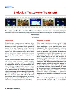
8 4. 500-1000 gpm of feed, all three should be used, even if the potentially scaling salts must be removed by chemical precipitation in front of the RO process. Up to now, resins, membranes, reverse osmosis, electro dialysis, chemichal/physical treatments were used. Even if all those technologies coming from the water treatment field proved to be rather effective, they do involve high costs in term of maintenance, energy and manpower. And they simply cannot face sudden variations in the flowrate and in the consumption of the water to be treated. What is more, they produce a very big volume of wastes (solutions and sludges containing high amounts of pollutants, deactivated or poisoned resins, etc.), which are extremely difficult and expensive to be Figure 1 Example of how a present ZLD- system is integrated in a power plant. Clarifier Figure 1 Example of how a present ZLD- system is integrated in a power plant. pH, neutralization er thicken different filters Waste water tank pre-treatment Effluent from plant Raw water and/or potable water Different filters EDR RO Brine evaporator Brine tank Feed tank Crystallizer reject reject solids Mixed bed Water tank Degasifier 6 Ionics EnChem.
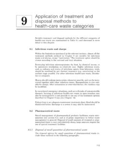
9 A ZLD-solution for the semiconductor industry Ionic claims that their water treatment system , the EnChem, removes more than 99% of the contaminating materials. The EnChem technology is also capable of reducing water usage during the semiconductor manufacturing process by up to 85% through reclaim. Ionics EnChem technology is a low pressure water treatment solution. It is specifically designed to reduce water consumption and operating costs. Figure 2 shows how the system works. clean water press solids Reaction tank Filtration Backflush Settling tank RO pH polymer Feed influent Figure 2 Ionics ZLD- system for the semiconductor industry The water to be treated has to go through four steps; through the reaction tank, on to the filtration, on to the backflush and finally to de-watering.
10 Each step is described below: Step 1. Reaction step. Influent waste water is pH adjusted, then mixed with organic and inorganic coagulent additives. The polymers react with the contaminants to form spheres. The reaction is complete in a few minutes. Step 2. Filtration. The filtration is accomplished through low pressure membranes. The clean water then exits the top of the filter while solids are retained on the filter membrane. Operating pressures remain below 15 psi (1 bar). Step 3. Backflush. The membranes are pulsed to remove solids and then solids are pumped to a settling tank. Step 4. Solids formation/De-watering. Solids are pumped to a holding tank for further settling. Conventional filter presses can be used to further separate and de-water solids. Overflow filter press water is returned to the reaction tank. 7 Tenergys plating waste water recovery system clean water effluent pre-treatment polishing plating Flash evaporator Ultra filtration Carbon filter Separate bed demine- ralizers Pumps with UV-sterilizer Figure 3 Tenergys ZLD- system for the plating industry.