Transcription of zz yy Stress & Strain: zx zy yz xy A review
1 1 zz Stress & Strain: Stress & Strain: A reviewA review xx yy yz xy xz zx zy yy xx zz yx1 of 79 Erik Eberhardt UBC Geological Engineering EOSC 433 Disclaimer before beginning your problem assignment:Disclaimer before beginning your problem assignment:Pick up and compare any set of textbooks on rock mechanics , soil mechanics or solid mechanics , and you will find that the discussion on Mohr Circles, Stress -strain analysis, matrix math, etc., either uses different conventions or contains a typo that will throw your calculations off. Clockwise is positive, clockwise is negative, mathematical shear off. Clockwise is positive, clockwise is negative, mathematical shear strain, engineering shear It all seems rather instead of becoming frustrated or condemning the proof-reader of a given textbook (or these notes), I like to look at it as a good lesson in not relying 100% on something, especially at the expense of your judgement. The notes that follow come from several sources and I have tried to eliminate the errors when I find them.
2 However, when using these notes to complete your problem assignment, try to also use your judgement as to 2 of 79 Erik Eberhardt UBC Geological Engineering EOSC 433whether the answer you obtain makes sense. If not, consult a different source to double check to see if there was an that note, if you find an error and/or a source that you would recommend as having given you a clearer understanding of a particular calculation, please let me know. 2 Understanding StressUnderstanding StressThere is a fundamental difference both conceptually and Stress is not familiar: it is a tensor quantity and tensors are not encountered in everyday is a fundamental difference, both conceptually and mathematically, between a tensor and the more familiar quantities of scalars and vectors: Scalar: a quantity with magnitude only ( temperature, time, mass).Vector: a quantity with magnitude and direction ( force, velocity, acceleration).3 of 79 Erik Eberhardt UBC Geological Engineering EOSC 433 Tensor: a quantity with magnitude and direction, and with reference to a plane it is acting across ( Stress , strain, permeability).
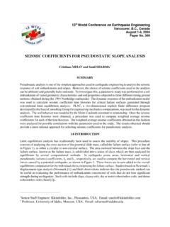
3 Both mathematical and engineering mistakes are easily made if this crucial difference is not recognized and Stress TensorThe Stress TensorThe second-order tensor which we will be examining has: - 9 components of which 6 are independent;- values which are point properties;- values which depend on orientation relative to a set of reference axes;- 6 of the 9 components becoming zero at a particular orientation;4 of 79 Erik Eberhardt UBC Geological Engineering EOSC 433pgp- three principal components;- complex data reduction requirements because two or more tensors cannot, in general, be averaged by averaging the respective principal of StressComponents of StressOn a real or imaginary plane through a material, there can be normal forcesand shear forces. These forces create the Stress tensor. The normal and shear Stress components are the normal and shear forces per unit ( )ShearStress ( )5 of 79 Erik Eberhardt UBC Geological Engineering EOSC 433It should be remembered that a solid can sustain a shear force, whereas a liquid or gas cannot.
4 A liquid or gas contains a pressure, which acts equally in all directions and hence is a scalar and Stress Force and Stress The reason for this is that it is only the force that is resolved in the first case ( vector), whereas, it is both the forceand the areaboth the forceand the areathat are resolved in the case of Stress ( tensor).In fact, the strict definition of a second-order tensor is a quantity that obeys certain transformation laws as the planes in question are rotated. This is 6 of 79 Erik Eberhardt UBC Geological Engineering EOSC 433pqwhy the conceptualization of the Stress tensor utilizes the idea of magnitude, direction and the plane in question .Hudson & Harrison (1997)4 Stress as a Point Property Stress as a Point Property Because the acting forces will vary according to the orientation of Awithin the slice, it is most useful to consider the l t( N/ A)d th h normal Stress ( N/ A)and the shear Stress ( S/ A)as the area Abecomes very small, eventually approaching of 79 Erik Eberhardt UBC Geological Engineering EOSC 433 Although there are practical limitations in reducing the size of the area to zero, it is important to realize that the Stress components are defined in this way as mathematical quantities, with the result that Stress is a point Components on an Infinitesimal Cube Stress Components on an Infinitesimal Cube For convenience, the shear and normal components of Stress may be resolved with reference to a given set of axes, usually a rectangular Cartesianx-y-zsystem.
5 In this case, the body can be considered to be cut at three orientations corresponding to the iibl f f b visible faces of a cube. & Harrison (1997)8 of 79 Erik Eberhardt UBC Geological Engineering EOSC 433To determine all the Stress components, we consider the normal and shear stresses on all three planes of this infinitesimal Tensor ConventionsStress Tensor ConventionsThus, we arrive at 9 Stress components comprised of 3 normaland 6 shearcomponents. The standard convention for denoting these components is that the first subscript refers to the plane onwhich the Stress component acts and the second subscript Hudson & Harrison (1997)9 of 79 Erik Eberhardt UBC Geological Engineering EOSC 433the Stress component acts, and the second subscript denotes the direction inwhich it acts. For normal stresses, compressionis positive. For shear stresses, positive stresses act in positive directions on negative faces(a negative face is one in which the outward normal to the face points in the negative direction).
6 Stress Components on a Cube Stress Components on a Cube Geotechnical Engineering-Right-hand systems-Compression positive-Tension negative10 of 79 Erik Eberhardt UBC Geological Engineering EOSC 433 Hudson & Harrison (1997)6 Symmetry in the Stress Matrix Symmetry in the Stress Matrix Although we arrive at 9 Stress components in the Stress matrix, we can assume that the body is in equilibrium. By inspecting the equilibrium of forces at a point in terms of equilibrium of forces at a point in terms of these 9 Stress components, we can see that for there to be a resultant moment of zero, then the shear stresses opposite from one another must be equal in , by considering moment ilib i d h d 11 of 79 Erik Eberhardt UBC Geological Engineering EOSC 433equilibrium around the x, yand zaxes, we find that: xy= yx yz= zy xz= zxSymmetry in the Stress Matrix Symmetry in the Stress Matrix If we consider the Stress matrix again, we find that it is symmetrical about the leading is clear then that the state of Stress at a point is defined completely by six independent components (3 normal and 3 shear).
7 Remembering back now, it can be noted that a scalarquantity can be completely specified by 1 valueand a vectorby 3 values, but a 12 of 79 Erik Eberhardt UBC Geological Engineering EOSC 433tensorrequires 6 values. Whatever method is used to specify the Stress state, there must be 6 independent pieces of information!!7 Principal StressesPrincipal StressesThe actual values of the 6 Stress components in the Stress matrix for a given body subjected to loading will depend on the orientation of the cube in the body itself. If we rotate the cube, it should be possible to find the directions in which the normal Stress components take on maximum and minimum values. It is found that in these directions the shear components on all faces of the cube become zero!symmetry13 of 79 Erik Eberhardt UBC Geological Engineering EOSC 433 The principal stressesare defined as those normal components of Stress that act on planes that have shear Stress components with zero magnitude!
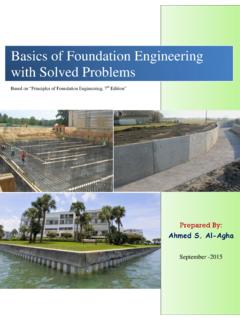
8 Example #1 Example #1Q. Add the following 2-D Stress states, and find the principal stresses and directions of the resultant Stress :Solve the problem graphically using a Mohr s circle Stress 14 of 79 Erik Eberhardt UBC Geological Engineering EOSC 433 Hudson & Harrison (1997)8 Example #1 (Solution) Example #1 (Solution) Q. Add the following 2-D Stress states, and find the principal stresses and directions of the resultant Stress step 1:Draw xyand lm axes for the first Stress state, and then plot the corresponding Mohr of 79 Erik Eberhardt UBC Geological Engineering EOSC 433 Example #1 (Solution)Example #1 (Solution)Q. Add the following 2-D Stress states, and find the principal stresses and directions of the resultant Stress The stresses transformed to the xyaxes are then:MPa16 of 79 Erik Eberhardt UBC Geological Engineering EOSC 4339 Example #1 (Solution)Example #1 (Solution)Q. Add the following 2-D Stress states, and find the principal stresses and directions of the resultant Stress step 2:Draw xyand lm axes for the second Stress state, and then plot the corresponding Mohr of 79 Erik Eberhardt UBC Geological Engineering EOSC 433 Example #1 (Solution)Example #1 (Solution)Q.
9 Add the following 2-D Stress states, and find the principal stresses and directions of the resultant Stress The stresses transformed to the xyaxes are then:MPa18 of 79 Erik Eberhardt UBC Geological Engineering EOSC 43310 Example #1 (Solution)Example #1 (Solution)Q. Add the following 2-D Stress states, and find the principal stresses and directions of the resultant Stress step 3: Adding the two xystress states givesMPa19 of 79 Erik Eberhardt UBC Geological Engineering EOSC 433 Example #1 (Solution)Example #1 (Solution)Q. Add the following 2-D Stress states, and find the principal stresses and directions of the resultant Stress step 4: Plotting the Mohr circle for the combined Stress state and reading off the principal stresses and the principal directions gives the required values 1= MPa 2= 27 6 MPa 20 of 79 Erik Eberhardt UBC Geological Engineering EOSC 433 2= MPa with 1being rotated 19 clockwise from the x-direction11 Example #2 Example #2Q.
10 A Stress state has been measured where: 1= 15 MPa, plunging 35 towards 085 2= 10 MPa, plunging 43 towards 217 8 MP l i 27 td 335 3= 8 MPa, plunging 27 towards 335 A. Perhaps before proceeding with this problem it would help to Find the 3-D Stress tensor in the right-handed x-y-zcoordinate system with xhorizontal to the east, yhorizontal to the north and zvertically of 79 Erik Eberhardt UBC Geological Engineering EOSC 433review some matrix Transformation Stress Transformation step 1 step 1 The matrix equation to conduct Stress transformation is as follows:.. where the Stress components are assumed known in the x-y-zcoordinate system and are required in another coordinate system l-m-ninclined with respect to the first. The term lis the direction cosine of the angle between the x-axis 22 of 79 Erik Eberhardt UBC Geological Engineering EOSC 433 The term lxis the direction cosine of the angle between the x-axis and l-axis.