Calculating Winding Temperature
Found 7 free book(s)
AN-1197Selecting Inductors for Buck Converters
www.ti.comcalculating the energy handling capability. The current is actually going to hit the internal ... voltsµsecs or ‘Et' which is simply the voltage across the winding of the inductor times the duration in µsecs ... • DC load of 1A (to ensure acceptable temperature rise, specify ΔT) OR steady state Energy handling
Overview of IEC/TS 60076-20 Ed. 1.0: Power Transformers ...
mddb.apec.orgwinding temperature rise + 20 °C, or rated winding temperature rise +yearly external cooling medium average temperature, whichever is higher. If a purchaser needs to compare transformer with different insulation systems and different average winding temperature rises, the reference temperature should be according to b) above.
Motor Calculations (Refer to pg. 49) see one-line diagram.
iwooten.comThe temperature rise is the difference of the motor winding temperature when running at its full potential and the ambient temperature. If the temperature rise does not exceed 40 C when running at its full potential, the motor will not be harmed. This is also a safety margin. Overloads protect the motor.

Flyback transformer design considerations for efficiency ...
www.ti.comdot-end of the primary winding is connected to ground, the dot-end of both the secondary and auxiliary windings will be negative and proportional to the input voltage. The respective rectifier diodes on those windings will thus be reverse-biased. While the primary switch remains on, current builds up in the primary winding at a rate dependent on
COMPUTATION OF TRANSFORMER LOSSES UNDER THE …
airccse.orgAdvanced Computing: An International Journal ( ACIJ ), Vol.2, No.6, November 2011 Here, PDC is Loss due to resistance of windings, losses in structural parts of transformer such as tank, clamps
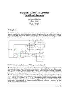
Design of a TL431-Based Controller for a Flyback ... - Plexim
www.plexim.comLoad resistance (±12 V winding) V c 15 Ω 1.96 7.5 Ω 2.22 4 Designing the Controller 4.1 Converter open-loop transfer function The first step in the design process is to obtain the open-loop transfer function of the converter. The voltage controller is then designed such that the closed-loop response of the system meets a specified bandwidth.
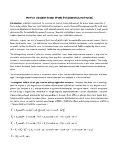
How an Induction Motor Works by Equations (and Physics)
www.brown.eduInduction Motor Equations ENGN1931F – Spring 2017 2 Let ω ω ω L R S and be the angular velocities of the magnetic field (line frequency), rotor, and slip respectively. For convenience we assume that ϕ= 0 at t = 0, which implies ϕ ω= R t and ω ω ω S L R= −. The flux in the single-turn coil on the rotor surface is