Transcription of Flyback transformer design considerations for efficiency ...
1 Flyback transformer design considerations for efficiency and EMIB ernard KeoghSystem and Solutions EngineerHigh Voltage Power SystemsIsaac CohenPrincipal System ArchitectLow Power Controller and ConverterTexas InstrumentsTexas Instruments 2 September 2016 Power Supply design Seminar 2016/17 IntroductionMany AC/DC and DC/DC power supplies, from very low power levels to as much as 150 W or more, use the Flyback converter. Often maligned and not always fully understood, the transformer is the heart of the Flyback power supply and probably the most important component. When designed and implemented well, the transformer can deliver the required performance cost-effectively. When poorly designed, it can cause EMI issues, low efficiency and possible thermal overstress paper will discuss the causes of the major losses in the Flyback transformer .
2 In particular, we will review core loss in light of recent research findings that highlight the significant impact of duty cycle and DC bias. The significant contribution of proximity effect on AC copper loss is also will review wire-size selection and winding methods to reduce AC copper loss. The effect of snubber clamp voltage levels and the often-neglected absorption of magnetizing energy by the snubber is also conducted EMI, we will outline the causes of common-mode (CM) EMI, suggesting various winding structures and techniques to ensure good CM , through several examples we will show how transformer construction can have a significant impact on both efficiency and conducted EMI. In these examples, we changed none of the other components only the transformer in order to demonstrate how a well-designed transformer can simultaneously improve both efficiency and Flyback topologyThe Flyback transformer is not really a transformer in the conventional sense; it is actually a coupled inductor.
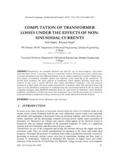
3 Figure 1 is a simplified schematic of a Flyback converter. The Flyback transformer in this example has three windings: primary, secondary and bias (sometimes called the auxiliary winding ).AC/DC power supplies widely use the Flyback converter given its simplicity and wide operating range, and because it eliminates the output filter inductor and free-wheeling rectifier required for forward-mode topologies. Three main topology components dominate Flyback -converter performance: the primary switch, secondary rectifier and transformer . This paper focuses on the importance of transformer design , since this single component has a profound impact on converter efficiency and electromagnetic interference (EMI). This paper will discuss the various conflicting design requirements, the often-neglected subtleties of core loss and snubber clamp level, and ways to improve transformer Instruments 3 September 2016 Power Supply design Seminar 2016/17 When the primary switch turns on, the input voltage is imposed across the primary winding .
4 Since the dot-end of the primary winding is connected to ground, the dot-end of both the secondary and auxiliary windings will be negative and proportional to the input voltage. The respective rectifier diodes on those windings will thus be reverse-biased. While the primary switch remains on, current builds up in the primary winding at a rate dependent on the input voltage and the primary magnetizing inductance, 1. Simplified schematic for a typical Flyback the current in the primary reaches the level required by the pulse-width-modulation (PWM) controller for regulation, the primary switch is turned off. The primary current then transfers to the secondary winding and the current decays at a rate proportional to VOUT. In this way, the energy stored in the transformer during the buildup of primary current gets released to the load and output capacitor during the flow of secondary current.
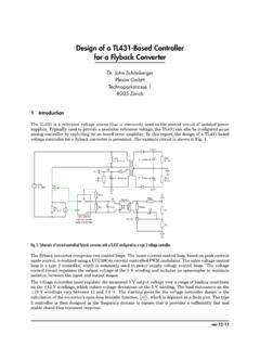
5 This is, of course, a simplified explanation; for more detailed descriptions of the Flyback topology and modes of operation, see references [1], [2] and [3].Based on this description, the Flyback transformer actually operates as a coupled inductor, where current builds up to a peak value in the primary winding and then decays back down in the secondary winding during the Flyback interval. Thus, when designing the Flyback transformer and assessing the losses, you must consider it more of an inductor than a operationFigure 2 shows the different operating phases of the Flyback converter during a single switching cycle, with the corresponding voltages and currents shown in Figure 3. During the primary switch on-time interval in Figure 2a, current flows from VOUTPRIMSECBIAS+VINPWMC ontrollerVDDCSDRVFBF igure 2.
6 Flyback converter operating intervals per switching cycle: primary switch on-time (a); primary switch turn-off, transition interval (b); secondary rectifier clamping and conduction interval ( Flyback interval) (c); discontinuous conduction mode (DCM) ringing interval (d).VOUTPRIMSEC+VINONVOUTPRIMSEC+VINOFFV OUTPRIMSEC+VINOFFVOUTPRIMSEC+VINOFF(a)(b )(c)(d)Texas Instruments 4 September 2016 Power Supply design Seminar 2016/17the input-voltage source through the transformer s magnetizing inductance, storing energy in the inductor air gap. During the transition interval in Figure 2b, the primary current transitions to the secondary, while the transformer s primary voltage swings positive. When the transformer primary voltage swings sufficiently more positive than VIN, the output Flyback diode becomes forward-biased and clamps the voltage.
7 Subsequently, during the interval in Figure 2c, the secondary current will decay linearly (since the voltage across the secondary winding is negative). During the interval in Figure 2c, some or all of the energy previously stored in the transformer s magnetizing inductance will be released to the secondary-side storage capacitor and to the discontinuous conduction mode (DCM), all of the energy stored in the inductance during the primary on-time interval is delivered to the secondary during the Flyback interval. In this mode, the secondary current decays to zero at the end of the Flyback interval. Subsequently, the interval in Figure 2d is the DCM ringing interval, where the magnetizing inductance resonates with the total parasitic capacitance on the switch node. The losses in the transformer core and the AC resistance (ACR) of the windings dampen this continuous conduction mode (CCM), the interval in Figure 2d does not occur because the primary on-time commences before the secondary current decays to zero.
8 In CCM, not all of the energy stored in the transformer s magnetizing inductance transfers to the secondary during each switching transformer lossesThe Flyback transformer is responsible for a large percentage of the total losses in a Flyback power stage. There are four categories of losses: Core losses. Copper ( winding ) losses. Transition losses. External losses occur in the transformer s ferrite core and depend on the core s flux density (amplitude, duty cycle and flux-density rate of change), frequency of operation, core size or volume, and Figure 3. Idealized Flyback converter voltages and currents, with highlighted operating intervals per switching cycle: primary switch on-time (a); primary switch turn-off, transition interval (b); secondary-rectifier clamping and conduction interval ( Flyback interval) (c); DCM ringing interval (d).
9 (a)(c)(b)(d )Texas Instruments 5 September 2016 Power Supply design Seminar 2016/17properties of the chosen ferrite material. Different materials optimized for different frequency and peak flux-density ranges will exhibit varying core-loss characteristics. We will describe core losses in more detail in the next flow of current through the resistance of the windings causes copper or winding losses. Most designers refer to it as copper loss because copper is by far the most commonly used wire material given its low resistance, ease of manufacture and wide loss breaks down further into DC loss and AC loss. DC loss is caused by DC or low-frequency root-mean-square (rms) current flowing through the DC resistance (DCR) of the winding . Maximizing the wire cross-sectional area and minimizing the wire length minimizes loss is caused by high-frequency electromagnetic effects from the magnetic field produced by the time-variant current flowing in the wires.
10 AC loss can be very significant, especially for large wire diameters. We will discuss AC losses in more detail losses refer to the losses associated with the transition or commutation of transformer current from the primary to secondary winding . In this region, the rate of change of the currents (di/dt) is very high, so the currents will have large high-frequency harmonic content. Also in this region, since both primary and secondary currents flow simultaneously, the Flyback transformer behaves more like a conventional high-frequency transformer , and so high-frequency effects and ACR are significant causes of loss. As transition loss is beyond the scope of this topic, see reference [4] for further the transformer itself incurs most of the losses, two significant external losses occur due to parasitic elements of the transformer .