Chapter 2 Transformer
Found 8 free book(s)
Chapter 5
pages.mtu.eduChapter 5 TRANSFORMERS. Objective • Understand the transformer nameplate • Describe the basic construction features of a transformer. ... the real power into transformer 2. The product of the voltage and the current gives the apparent power, S. 3. Science the real power is known, we can find the power factor and the impedance angle.
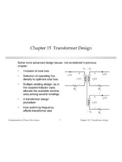
Chapter 15 Transformer Design
ecee.colorado.eduFundamentals of Power Electronics Chapter 15: Transformer design13 2. Evaluate peak ac flux density At this point, one should check whether the saturation flux density is exceeded. If the core operates with a flux dc bias Bdc, then B + Bdc should be less than the saturation flux density Bsat. If the core will saturate, then there are two choices:

Chapter 2 Grounding & Shielding - TU Delft
qtwork.tudelft.nlChapter 2 Grounding & Shielding Safety, system protection and performance are the three main reasons to earth a system. Not all electronic equipment needs to be connected to earth to work, ... derived systems or sources (transformer, generators, UPSs, etc.). The first requirement is to bond the neutral or secondary grounded circuit conductor to the

Transformer Dry Type Install Best Practices White ... - Eaton
www.eaton.comtransformer can be readily accomplished at a suitably clean and dry location on the site. ... Chapter II, Part 431 (in Appendix A of Subpart K 2016), the new efficiency levels are more commonly referred to as the DOE 2016 Efficiency levels. As of January 1, 2016, these new efficiency levels have gone
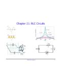
Chapter 21: RLC Circuits
www.phys.ufl.eduPHY2054: Chapter 21 19 Power in AC Circuits ÎPower formula ÎRewrite using Îcosφis the “power factor” To maximize power delivered to circuit ⇒make φclose to zero Max power delivered to load happens at resonance E.g., too much inductive reactance (X L) can be cancelled by increasing X C (e.g., circuits with large motors) 2 P ave rms=IR rms ave rms rms rms cos
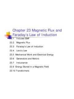
Chapter 23 Magnetic Flux and Faraday’s Law of Induction
physics.gsu.eduChapter 23 Magnetic Flux and Faraday’s Law of Induction 23.1 Induced EMF 23.2 Magnetic Flux 23.3 Faraday’s Law of Induction 23.4 Lenz’s Law 23.5 Mechanical Work and Electrical Energy 23.6 Generators and Motors 23.7 Inductance 23.9 Energy Stored in a …

Chapter 12 Alternating-Current Circuits
web.mit.edu===ω (12.2.2) where VR0=V0, and IR0=VR0R is the maximum current. Comparing Eq. (12.2.2) with Eq. (12.1.2), we findφ=0, which means that IR (t)and are in phase with each other, meaning that they reach their maximum or minimum values at the same time. The time dependence of the current and the voltage across the resistor is depicted in Figure ...