Circuit Rlc
Found 10 free book(s)
Chapitre 3 : Le circuit RLC série
d1n7iqsz6ob2ad.cloudfront.netLa valeur de R dans un circuit RLC détermine le régime de fonctionnement de celui-ci: pseudo-périodique ou apériodique. d- Régime périodique Si l’amortissement est négligeable (ce qui ne peut exister en pratique pour un circuit libre), le système est le siège d’oscillations non amorties, le régime est alors périodique.

AC CIRCUITS: RLC SERIES CIRCUIT INTRODUCTION
www.austincc.eduJul 11, 2007 · 8D-RLC Series Circuit 07-07-11.doc - 2 - frequency version. The circuit component values have been specifically chosen to enhance the resonance effect on the peaking of the current and to make it easier to measure the phase angle and to avoid certain equipment limitations. Setting Up The Circuit

RLC Resonant Circuits - University of Cambridge
mlg.eng.cam.ac.ukowing in the circuit, however for a parallel RLC circuit this will not be the same. Similarly, V Crms is the rms voltage across the capacitor. For the simple parallel RLC circuit shown in gure 5 this is just equal to the rms supply voltage but for the …

Chapter 12 Alternating-Current Circuits
web.mit.eduBefore examining the driven RLC circuit, let’s first consider the simple cases where only one circuit element (a resistor, an inductor or a capacitor) is connected to a sinusoidal voltage source. 12.2.1 Purely Resistive load Consider a purely resistive circuit with a resistor connected to an AC generator, as shown in Figure 12.2.1.

Lab Report 2 RLC Circuits - Obaidtech
www.obaidtech.com4.3 Exercise 3 - Resonance of series RLC circuits Finally we were required to observe the e ects of resonance frequency in a series RLC circuit. We connected the circuit as shown below and then used the equation introduced above to nd the resonance frequency and then adjusted the function generator to set as to the one we obtained from the ...
SECTION 3: SECOND-ORDER FILTERS - College of Engineering
web.engr.oregonstate.eduK. Webb ENGR 202 3 Second-Order Circuits Order of a circuit (or system of any kind) Number of independent energy -storage elements Order of the differential equation describing the system Second-order circuits Two energy-storage elements Described by second -order differential equations We will primarily be concerned with second- order RLC circuits

User Guide - Trane
www.trane.comSystem/Circuit Selection Buttons On some report and setting screens, radio buttons on the top of the screen shall be presented to allow the user to select subscreens based on system-level data and per-circuit data. For single-circuit units with system/circuit selection buttons, the buttons shall be labeled (in English) “System” and “Ckt”.

XII. AC Circuits - Worked Examples
web.mit.eduExample 2: Series RLC Circuit Suppose an AC generator with Vt( )=(150V)sin(100πt)is connected to a series RLC Calculate the following: (a) VR0, VL0 and VC0, the maximum voltage drops across each circuit element, and (b) the maximum voltage drop across points b and d shown in the figure. Solution: (a) The inductive reactance, capacitive reactance and the …
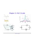
Chapter 21: RLC Circuits - Department of Physics
www.phys.ufl.eduPHY2054: Chapter 21 2 Voltage and Current in RLC Circuits ÎAC emf source: “driving frequency” f ÎIf circuit contains only R + emf source, current is simple ÎIf L and/or C present, current is notin phase with emf ÎZ, φshown later sin()m iI t I mm Z ε =−=ωφ ε=εω m sin t ω=2πf sin current amplitude() m iI tI mm R R ε ε == =ω

CIRCUITS LABORATORY EXPERIMENT 3 AC Circuit Analysis
classes.engineering.wustl.eduAC Circuit Analysis 3.1 Introduction The steady-state behavior of circuits energized by sinusoidal sources is an important area of study for several reasons. First, the generation, transmission, ... both RC and RLC circuits will be examined when driven by a sinusoidal source at a 3-1. given frequency. Subsequently, the frequency response of ...