Search results with tag "Rlc circuits"

Lab Report 2 RLC Circuits - Obaidtech
www.obaidtech.com4.3 Exercise 3 - Resonance of series RLC circuits Finally we were required to observe the e ects of resonance frequency in a series RLC circuit. We connected the circuit as shown below and then used the equation introduced above to nd the resonance frequency and then adjusted the function generator to set as to the one we obtained from the ...
Chapter 8 Natural and Step Responses of RLC Circuits
www.ee.nthu.edu.twWhat are the initial conditions in an RLC circuit? ... Comparisons between: (1) natural & step responses, (2) parallel, series, or general RLC. 3 Section 8.1, 8.2 The Natural Response of a Parallel RLC Circuit 1. ODE, ICs, general solution of parallel voltage 2. Over-damped response 3. Under-damped response 4. Critically-damped response . 4
Chapter 21: RLC Circuits - Department of Physics
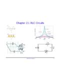
www.phys.ufl.eduPHY2054: Chapter 21 2 Voltage and Current in RLC Circuits ÎAC emf source: “driving frequency” f ÎIf circuit contains only R + emf source, current is simple ÎIf L and/or C present, current is notin phase with emf ÎZ, φshown later sin()m iI t I mm Z ε =−=ωφ ε=εω m sin t ω=2πf sin current amplitude() m iI tI mm R R ε ε == =ω
Chapter 21: RLC Circuits
www.phys.ufl.eduPHY2054: Chapter 21 2 Voltage and Current in RLC Circuits ÎAC emf source: “driving frequency” f ÎIf circuit contains only R + emf source, current is simple ÎIf L and/or C present, current is notin phase with emf ÎZ, φshown later sin()m iI t I mm Z ε =−=ωφ ε=εω m sin t ω=2πf sin current amplitude() m iI tI mm R R ε ε == =ω

XII. AC Circuits - Worked Examples
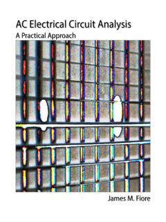
web.mit.eduExample 2: Series RLC Circuit Suppose an AC generator with Vt( )=(150V)sin(100πt)is connected to a series RLC Calculate the following: (a) VR0, VL0 and VC0, the maximum voltage drops across each circuit element, and (b) the maximum voltage drop across points b and d shown in the figure. Solution: (a) The inductive reactance, capacitive reactance and the …

State Space Approach to Solving RLC circuits
web.mit.edu– Solve RLC circuit for i 1(t) and i 2(t) using the node or loop method • We will use node method in our examples • Note that the equations at e 1 and e 2 give us i 1 and i 2 directly in terms of e 1, e 2, e 3 – Also note that v 1 = e 1 and v 2 = e 2 – Equation at e 3 gives e 3 in terms of e 1 and e 2 We!have, d dt v 1 (t)= i 1 (t) C ...
AC Electrical Circuit Analysis - MVCC
www2.mvcc.eduChapters on series, parallel and series-parallel RLC circuits commence. Following these, network theorems along with nodal and mesh analysis are discussed for the AC case. The text completes with chapters on AC power, resonance, and introductions to polyphase systems and magnetic circuits.
Solving circuits directly using Laplace
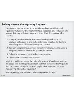
tuttle.merc.iastate.eduAnalyze the circuit in the time domain using familiar circuit analysis techniques to arrive at a differential equation for the time-domain quantity of interest (voltage or current). 2. Perform a Laplace transform on the differential equation to arrive a ... C in the RLC circuit below. The input is a step function, v i ...

Chapter 12 Alternating-Current Circuits
web.mit.eduBefore examining the driven RLC circuit, let’s first consider the simple cases where only one circuit element (a resistor, an inductor or a capacitor) is connected to a sinusoidal voltage source. 12.2.1 Purely Resistive load Consider a purely resistive circuit with a resistor connected to an AC generator, as shown in Figure 12.2.1.
Q Calculations of L-C Circuits and Transmission Lines: A ...
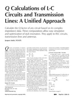
www.ve2azx.net44 Sep/Oct 2006 R s and X and are the real and imaginary com- ponents of the RLC circuit impedance Z and ω= π2f. Equation 2 may be simplified as: r a s FL Q Rf C (Eq 3) where Qa is the Q factor below the resonant frequency Fr and f is the frequency at which Qa is …
Circuits RC, RL, RLC - gilbert.gastebois.pagesperso-orange.fr
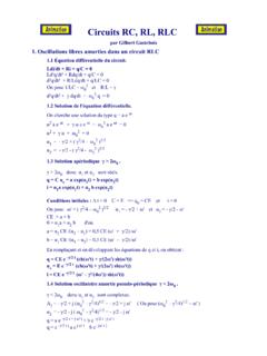
gilbert.gastebois.pagesperso-orange.frCircuits RC, RL, RLC par Gilbert Gastebois 1. Oscillations libres amorties dans un circuit RLC 1.1 Équation différentielle du circuit. Ldi/dt + Ri + q/C = 0

RLC Resonant Circuits - University of Cambridge
mlg.eng.cam.ac.ukowing in the circuit, however for a parallel RLC circuit this will not be the same. Similarly, V Crms is the rms voltage across the capacitor. For the simple parallel RLC circuit shown in gure 5 this is just equal to the rms supply voltage but for the …

The RLC Circuit
www.math.ubc.caThe RLC Circuit The RLC circuit is the electrical circuit consisting of a resistor of resistance R, a coil of inductance L, a capacitor of capacitance C and a voltage source arranged in series.

Chapitre 3 : Le circuit RLC série
d1n7iqsz6ob2ad.cloudfront.netLa valeur de R dans un circuit RLC détermine le régime de fonctionnement de celui-ci: pseudo-périodique ou apériodique. d- Régime périodique Si l’amortissement est négligeable (ce qui ne peut exister en pratique pour un circuit libre), le système est le siège d’oscillations non amorties, le régime est alors périodique.

AN11160 Designing RC snubbers - Nuts & Volts Magazine
www.nutsvolts.comDocument information AN11160 Designing RC snubbers Rev. 1 — 25 April 2012 Application note Info Content Keywords RC snubber, commutation, reverse recovery, leakage inductance, parasitic capacitance, RLC circuit and damping, MOSFET

RLC Circuit - Iowa State University
apps-dso.sws.iastate.eduRLC Circuit: Phasors: ALWAYS draw the diagram!! 22 22 () tan L C LRC L C Z X X R E V V V E IZ XX R M Related Problems 1) You have a 200 ohm resistor, a 0.400-H inductor. Suppose you take the resistor and inductor and make a series circuit with a voltage source that has voltage amplitude 30.0 V