Ac Electrical Circuit Analysis
Found 7 free book(s)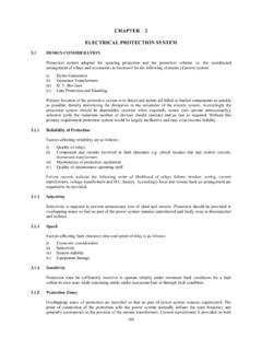
CHAPTER – 3 ELECTRICAL PROTECTION SYSTEM
www.iitr.ac.inA circuit breaker is an interrupting device designed for normal switching functions as well as for fault interruption. Circuit breakers offer considerable flexibility and are available in variety of voltage, current, and fault current interrupting ratings. High-voltage circuit breakers are equipped with separate electrically

Power System Analysis
research.iaun.ac.ir1.2. Fault Current Analysis 3 1.2 Fault Current Analysis In the lectures Elektrische Energiesysteme it was studied how to calculate fault currents, e.g. short circuit currents, for simple systems. This analysis will now be extended to deal with realistic systems including several gener-ators, lines, loads, and other system components.

Lecture #4 BJT AC Analysis
www.bu.edu.eg• The dc analysis of npn and pnp configurations is quite different in the sense that the currents will have opposite directions and the voltages opposite polarities. • However, for an ac analysis where the signal will progress between positive and negative values, the ac equivalent circuit will be the same. npn versus pnp J-601-4 l-a
BASIC ELECTRICAL ENGINEERING
www.jcboseust.ac.inThe capacitor disconnects current in alternating current (AC) circuits. F. INDUCTOR: -An inductor is a passive electronic component that stores energy in the form of magnetic field. An inductor consists of wire loop or coil. Inductor can be used in motors by creating mechanical energy from its electrical and magnetic energy. Inductor

RLC Resonant Circuits - University of Cambridge
mlg.eng.cam.ac.ukthat the circuit exhibits voltage ampli cation properties. At the resonant frequency, v C v = 1 j! 0RC v L v = j! 0L R (8) It is important to note that as this is a passive circuit the total amount of power dissipated is constant. 3 Parallel Circuit Figure 5 shows a parallel resonant RLC circuit. It is the ‘dual’ of the series circuit in ...

CHARGE AND DISCHARGE OF A CAPACITOR
faraday.physics.utoronto.caAlternating Current (AC) “square wave ” voltage supply to charge the capacitor through the resistor many times per second, first in a positivedirection and then in a negative direction. The charging process also exhibits the same exponential behaviour as …
Simulating Switched-Capacitor Filters with SpectreRF
designers-guide.orgSimulating Switched-Capacitor Filters with SpectreRF A Simple Track and Hold 4 of 25 The Designer’s Guide Community www.designers-guide.org (freq2 = 10.1kHz ampl2 = 0 fundname2 = “input2”).Initially, the waveshape is set to a fixed value by type = dc.Later, the alter statement named enableTone1 changes the waveshape type to sine to enable the first tone.