Switched Capacitor
Found 10 free book(s)
LMC7660 Switched Capacitor Voltage Converter datasheet ...
www.ti.comLMC7660 Switched Capacitor Voltage Converter Check for Samples: LMC7660 1FEATURES DESCRIPTION The LMC7660 is a CMOS voltage converter capable 2• Operation Over Full Temperature and Voltage Range without an External Diode ofconverting a positive voltage in the range +1.5V to +10V to the corresponding negative voltage of

Introduction to Switched-Capacitor Circuits
www.seas.ucla.eduanalyze switched-capacitor amplifiers, considering unity-gain, noninverting, and multiply-by-two topologies. Finally, we examine a switched-capacitor integrator. 12.1 General Considerations In order to understand the motivation for sampled-data circuits, let us first consider the simple continuous-time amplifier shown in Fig. 12.1(a).
Simulating Switched-Capacitor Filters with SpectreRF
designers-guide.orgSimulating Switched-Capacitor Filters with SpectreRF A Simple Track and Hold 4 of 25 The Designer’s Guide Community www.designers-guide.org (freq2 = 10.1kHz ampl2 = 0 fundname2 = “input2”).Initially, the waveshape is set to a fixed value by type = dc.Later, the alter statement named enableTone1 changes the waveshape type to sine to enable the first tone.

LT1065/LT1054L (Rev. I) - Analog Devices
www.analog.comSwitched-Capacitor Voltage Converter with Regulator The LT®1054 is a monolithic, bipolar, switched-capacitor voltage converter and regulator. The LT1054 provides higher output current than previously available converters with significantly lower voltage losses. An adaptive switch driver scheme optimizes efficiency over a wide range of

MAX1044/ICL7660 - Switched-Capacitor Voltage Converters
datasheets.maximintegrated.comswitched-capacitor voltage converters that invert, double, divide, or multiply a positive input voltage. They are pin compatible with the industry-standard ICL7660 and LTC1044. Operation is guaranteed from 1.5V to 10V with no external diode over the full temperature range. They deliver 10mA with a 0.5V output drop. The MAX1044 has
How to Implement a MOSFET with a Gate Driver
www.egr.msu.eduNov 13, 2014 · capacitor, which must be charged or discharged each time the MOSFET is switched on or off respectively . As a transistor requires a particular gate voltage in order to switch on, the gate capacitor must be charged to at least the required gate voltage for the transistor to be switched on.

How to get the best ADC accuracy in STM32 …
www.st.comdesign is based on the switched-capacitor technique. The following figures (Figure 1. to . Figure 6) explain the principle of ADC operation. The example given below shows only the first steps of approximation but the process continues till the LSB is reached. Figure 1. Basic schematic of SAR switched-capacitor ADC (examp le of 10-bit ADC) 1.

Review of Capacitor Bank Control Practices
prorelay.tamu.edu• Manual control – capacitor bank will be switched On/Off by the operator, based on needs. We’ll review these methods to elaborate on which method is most appropriate for certain application. A. Time-based automatic control Timed-based control is beneficial when the VAR demand pattern is well known during each day and ...
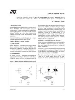
Drive circuits for Power MOSFETs and IGBTs
www.st.comcapacitor when discussing drive circuits. 2. IGBT / MOSFET DRIVE BASICS 2.1 Gate vs Base Power MOSFETs and IGBTs are simply voltage driven switches, because their insulated gate behaves like a capacitor. Conversely, switches such as triacs, thyristors and bipolar transistors are “current” controlled, in the same way as a PN diode. 2.2 ...
POWERFACTOR CORRECTION (pfc)
electrical.theiet.orgCapacitor module designed for local correction of individual loads such as single motors, starters or control gear incorporating an integral circuit breaker for independent isolation and overload protection. [Illustration courtesy of PFC Engineering Ltd] A 324 kVAr, automatic power factor correction unit. [Illustration courtesy of PFC ...