Common Capacitor
Found 7 free book(s)
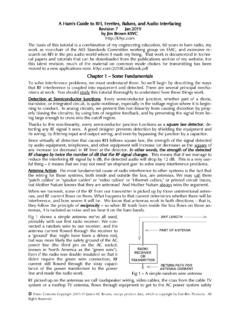
Introduction to Switched-Capacitor Circuits
www.seas.ucla.eduIn this chapter, we study a common class of discrete-time systems called “switched-capacitor (SC) circuits.” Our objective is to provide the foundation for more advanced topics such as filters, comparators, ADCs, and DACs. Most of our study deals with switched-capacitor amplifiers but

AD797 (Rev. K)
www.analog.comCommon Mode 5 5 pF OUTPUT RESISTANCE A V = 1, f = 1 kHz 3 3 mΩ POWER SUPPLY Operating Range ±5 ±18 ±5 ±18 V Quiescent Current ±5 V, ±15 V 8.2 10.5 8.2 10.5 mA 1 Full power bandwidth = slew rate/2π V PEAK. 2 Specified using external decompensation capacitor. 3 Output current for |V S − V
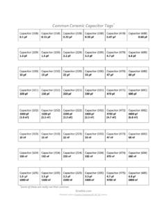
Common Ceramic Capacitor Tags - Grathio
grathio.comCommon Ceramic Capacitor Tags* Capacitor (108) 0.1 pF Capacitor (158) 0.15 pF Capacitor (228) 0.22 pF Capacitor (338) 0.33 pF Capacitor (478) 0.47 pF
A Ham's Guide to RFI, Ferrites, Baluns, and Audio ...
www.audiosystemsgroup.comA common mode signal is one that places equal voltage on all conductors – that is, the voltage be-tween the two ends of the cable are different, but there is no voltage between the conductors. An-tenna action produces a common mode voltage and current along a cable. The antenna current in-duced on audio and video wiring is a common mode ...

Common Mistakes in DC/DC Converters and How to Fix …
www.ti.comthrough a number of common mistakes in point-of-load DC/DC converter design and testing. With an engaging, interactive format, this session covers issues found in converter capabilities, component ... converter, series capacitor buck converter [1][2] and many others may also be used, this discussion focuses on the buck converter for simplicity.
Lecture Notes for Analog Electronics - University of Oregon
pages.uoregon.eduThis is the usual capacitor \charge up" solution. Similarly, a capacitor with a voltage Vi across it which is discharged through a resistor to ground starting at t = 0 (for example by closing a switch) can in similar fashion be found to obey V(t)=Vie−t=RC 2.0.5 The \RC Time"
S-Domain Analysis
homepages.cae.wisc.edusources to represent capacitor and inductor initial conditions Step 1: Select a reference node. Identify a node voltage at each of the non-reference nodes and a current with every element in the circuit Step 2: Write KCL connection constraints in terms of the element currents at the non-reference nodes