Marking Terminal
Found 11 free book(s)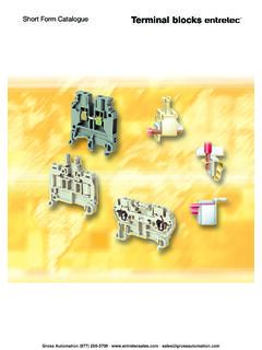
Catalogue Terminal blocks - Entrelec Sales
entrelecsales.comTerminal blocks for railway applications .....page 87 to 97 Pluggable terminal blocks .....page 98 to 100 ... Marking table Horizontal marking Vertical marking Rated wire size : 0.5 to 16 mm² (22 to 8 AWG) Spacing : 6 to 10 mm (.236" to .394") 5 to …

MC33269 - Voltage Regulator Adjustable Output, Low …
www.onsemi.comHeatsink surface (shown as terminal 4 in case outline drawing) is connected to Pin 2. See general marking information in the device marking section on page 8 of this data sheet. DEVICE MARKING INFORMATION 1. GND/Adj 2. Vout 3. Vin

Rapid React Layout and Marking Diagram
firstfrc.blob.core.windows.netA Marking A B B C C D D 4 4 3 3 2 2 1 1. Notes: 1. Bill of Materials and model do not represent all CARGO to be staged and used in a match. 4 8 5 9 12 3 10 11 2 1 6 7 ... 7 GE-22000 Terminal Assembly 2 8 GE-22100 Hangar 2 9 GE-22300 Hub 1 10 GE-22497 Cargo - Red 8 11 GE-22498 Cargo - Blue 8 12 GE-22600 Angled cable protector 1 DO NOT SCALE DRAWING
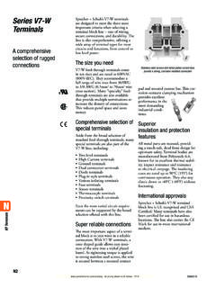
Series V7-W Terminals - Sprecher + Schuh
www.sprecherschuh.comMarking Systems Blank Tags (cards of 100) V7-SM5X9 5V7-SM6X12 V7-SM5X12 5 5 Pre-printed Tags (sticks of 10) V7-MP5 10 V7-MP 10 V7-MP 10 Terminal Block Specifications Approvals ® IEC ® IEC ® IEC Voltage Rating 600V 600V 800V 600V 600V 800V 600V 600V 800V AC/DC AC/DC AC/DC AC/DC AC/DC AC/DC AC/DC AC/DC AC/DC
Surface Mount Multilayer Ceramic Chip Capacitors (SMD ...
content.kemet.comto establish pliability, while maintaining terminal strength, solderability and electrical performance. This technology was developed in order to address the primary failure mode of MLCCs – flex cracks, which are typically the result ... The terms "Marked" and "Unmarked" pertain to laser marking option of capacitors. All packaging options ...
Metallized Polypropylene DC-Link Film Capacitor Automotive ...
www.vishay.comSPECIAL CODE FOR TERMINAL 2 2 pins 4 4 pins P2 = 10.2 mm 5 4 pins P2 = 20.3 mm (1) Customized TOLERANCE 4 ± 5 % METALLIZED POLYPROPYLENE P1 (mm) PITCH CODE 27.5 K 37.5 P 52.5 Y h w Ø dt I 6 - 1 P1 ± 0.4 - PCM 27.5 mm P1 ± 0.5 - PCM ≥ 37.5 mm P1 P1 ± 0.5 Marking I w 6 - 2 Ø dt P2 ± 0.5 h P1 P2 P2

Mark Scheme (Results) June 2014 - Edexcel
qualifications.pearson.comGeneral Marking Guidance •All candidates must receive the same treatment. Examiners must mark the first candidate in exactly the same way as they mark ... How results indicate terminal velocity achieved; Ignore . ticker-timer . measurement of mass . condone tape measure .

Mark Scheme (Results) January 2014 - Edexcel
qualifications.pearson.comMar 06, 2014 · General Marking Guidance All candidates must receive the same treatment. Examiners must mark the first candidate in exactly the same way as they mark the last. Mark schemes should be applied positively. Candidates must be rewarded ... allow constant speed for terminal velocity but
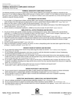
Safety, Service, and Security An Internationally ...
www.chp.ca.gov•Marking requirements for packages, containers, and vehicles. Title 13 CCR Section 1161.3, and Title 49 CFR Section 172.300 ... A terminal rated unsatisfactory is one showing a lack of compliance which could jeopardize the safety of passengers and/or the

TERMINAL MARKINGS AND INTERNAL WIRING DIAGRAMS …
www.rses.orgthe terminal marking shall be determined as follows:* For the purpose of assigning terminal markings, the main winding is assumed to be divided into two halves, and T1 and T2 should be assigned to one half and T3 and T4 to the other half.* For the purpose of assigning terminal markings, the auxiliary winding (if present) is assumed to
TERMINAL MARKINGS AND INTERNAL WIRING …
www.rses.orgthe terminal marking shall be determined as follows:* For the purpose of assigning terminal markings, the main winding is assumed to be divided into two halves, and T1 and T2 should be assigned to one half and T3 and T4 to the other half.* For the purpose of assigning terminal markings, the auxiliary winding (if present) is assumed to