Terminal markings and internal wiring
Found 10 free book(s)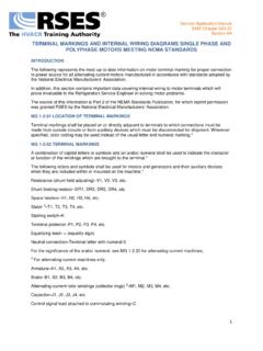
TERMINAL MARKINGS AND INTERNAL WIRING …
www.rses.orgService Application Manual SAM Chapter 620-37 Section 6A . TERMINAL MARKINGS AND INTERNAL WIRING DIAGRAMS SINGLE PHASE AND POLYPHASE MOTORS MEETING NEMA STANDARDS
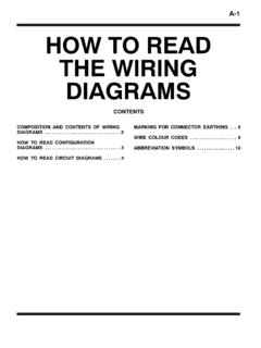
A-1 HOW TO READ THE WIRING DIAGRAMS
www.evoscan.comHOW TO READ THE WIRING DIAGRAMS - Markings for Connector Earthing A-7 Item No. Connector/Earthing Symbol Contents Connector and terminal marking 1 Male connector Male terminal Themaleandfemaleterminalsare

Varispeed V7 INSTRUCTION MANUAL - star …
www.star-circuit.com3 PRECAUTIONS FOR UL/cUL MARKING • Do not connect or disconnect wiring, or perform signal checks while the power supply is turned ON. • The Inverter internal capacitor is still charged even after the power supply

VS-606V7 Series INSTRUCTION MANUAL - Huppertz
www.huppertz.nl4 WARNINGS FOR UL/cUL MARKING • Do not connect or disconnect wiring, or perform signal checks while the power supply is turned ON. • The Inverter internal capacitor is still charged even after the power supply
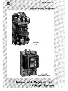
GI-2.0: Typical Wiring Diagrams - Rockwell …
literature.rockwellautomation.comWiring Diagrams ww introduction This booklet has been prepared as a guide to some of the useful ways Allen-Bradley’s manual and magnetic across-the-line starters

TEST REPORT IEC EN 61010-1 Safety requirements …
www.valco.itpag 9 of 56 Report No. 55790TRFSAF Clause Requirement + Test Result – Remark Verdict 5 MARKING AND DOCUMENTATION — 5.1.1 General — Required equipment markings are: —
Technical Information RoHS - MAMAC Systems, …
www.mamacsys.comModel HU-226 Technical Information TI.226-04 TEMP / HUMIDITY TRANSDUCER Page 3 of 4 RoHS TYPICAL APPLICATIONS (wiring diagrams) Neutral + Hot Controller / …

Solenoid Valves- D03 & D05 - Hyvair
www.hyvair.comSOLENOID VALVES D03 & D05 SERIES 35- SOLENOID VALVES NFPA SIZE: D03 & D05 Series 35 High Flow High Pressure Directional Valves 31341 Friendship Drive, Magnolia, TX 77355 • Tel.: 281-259-7768 Fax: 281-259-7249 • www.hyvair.com
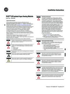
1794-IN038E-EN-P FLEX I/O Isolated Input Analog …
literature.rockwellautomation.comFLEX™ I/O Isolated Input Analog Module 3 Publication 1794-IN038E-EN-P - November 2011 5. If continuing DC common to the next base unit, connect a jumper from

Installation & Maintenance Instructions SERIES …
www.lesman.comI&M No.V6583R9 Page3of6(Section1of2) EASCO Valve, Inc.R 50 Hanover Road, Florham Park, New Jersey 07932 www.ascovalve.com Installation of Solenoid ...
Similar queries
TERMINAL MARKINGS AND INTERNAL WIRING, TERMINAL MARKINGS AND INTERNAL WIRING DIAGRAMS, TO READ THE WIRING DIAGRAMS, Markings, Terminal, Varispeed V7 INSTRUCTION MANUAL, Wiring, Internal, VS-606V7 Series INSTRUCTION MANUAL, Typical Wiring Diagrams, Rockwell, Solenoid Valves- D03 & D05, SOLENOID VALVES D03 & D05, O Isolated Input Analog, O Isolated Input Analog Module, Installation & Maintenance Instructions SERIES