Output Digital
Found 7 free book(s)
Measuring the Digital Economy: An Update Incorporating ...
www.bea.govSplitting the output of partially digitalcategories into digital and nondigital portions will require additional source data and other resources t o accurately identify the share of output that i s in scope for the digital economy. The work to identify data to include partially digital good s and services is ongoing.

Product Bulletin Fisher FieldVue Digital Valve Controller ...
www.emerson.com7D Supply & Output gauges, dual scaled 0-60 psig, 0-0.4 Mpa 7E Supply & Output gauges, dual scaled 0-60 psig, 0-4 kgm2 7F Supply & Output gauges, dual scaled 0-160 psig, 0-11 bar 7G Supply & Output gauges, dual scaled 0-160 psig, 0-1.1 Mpa 7H Supply & Output gauges, dual scaled 0-160 psig, 0-11 kgm2 8. Threaded Connections*

MSD Digital 6A and 6AL Ignition Control 6A - PN 6201/62013 ...
documents.holley.comDIGITAL OPERATION The Digital 6A and 6AL use a high speed RISC microcontroller to control the ignition's output while constantly analyzing the various inputs such as supply voltage, trigger signals and rpm. The high speed controller can make extremely quick compensations to the output voltage, multiple spark

Flip-Flops and Sequential Circuit Design
web.ece.ucsb.eduFebruary 13, 2012 ECE 152A - Digital Design Principles 5 Reading Assignment Brown and Vranesic (cont) 8 Synchronous Sequential Circuits 8.1 Basic Design Steps 8.1.1 State Diagram 8.1.2 State Table 8.1.3 State Assignment 8.1.4 Choice of Flip-Flops and Derivation of Next-State and Output Expressions 8.1.5 Timing Diagram
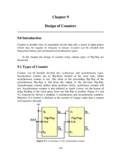
Chapter 9 Design of Counters - Universiti Tunku Abdul Rahman
staff.utar.edu.myfrom clock pulse to output of flip-flop 0 Q 0, from output of flip-flop 0 Q 0 to output flip-flop 1 Q 1, and from output of flip-flop 1 Q 1 to output flip-flop 2 Q 2. If the output Q 1 is AND’ed with output Q0, the ideal result i.e. the assumption of no propagation delay is shown in …

PS3.6 - DICOM
dicom.nema.org[ACR-NEMA 300] ACR-NEMA. 1988. Digital Imaging and Communications. [ASTM E2339-11] ASTM. 2011. Standard Practice for Digital Imaging and Communication in Nondestructive Evaluation (DICONDE). [IEC 61217] IEC. 2011. Ed 2. Radiotherapy Equipment - Coordinates, Movements and Scales. [ISO 8649] ISO. 1988.

EXPERIMENT 3: TTL AND CMOS CHARACTERISTICS
www.classe.cornell.edu3.3 TTL logic the limiting value is the LOW fanout. Some TTL structures have fan-outs of at least 20 for both logic levels. A voltage transfer curve is a graph of the input voltage to a gate versus its output voltage; Figure 3.2 shows the transfer curve for TTL inverter without any fanout.