Snubber Circuit
Found 9 free book(s)
RC snubber circuit design for TRIACs - STMicroelectronics
www.st.comSnubber circuit functions and drawback AN437 4/18 Figure 4. Z0103 TRIAC turn-off on inductive load without and with snubber circuit (C = 10 nF and R = 2.7 kΩ) The snubber circuit design, detailed in Section 2: How to design snubber circuit for turn-off improvement, is a trade-off between the maximum peak off-state voltage under pulse conditions (VDSM / VRSM), the …

Chapter 5 Protection Circuit Design - Fuji Electric
www.fujielectric.comSnubber circuit schematic Circuit features (comments) Main application C snubber circuit • This is the simplest circuit • The LC resonance circuit, which consists of a main circuit inductance coil and snubber capacitor, may cause the C-E voltage to oscillate.

Reducing noise on the output of a switching regulator
www.ti.comSnubber circuit A snubber circuit contains a resistor and capacitor that should dampen the switch-node ringing by absorbing the energy stored in the parasitic elements of the MOSFETs and printed circuit board (PCB). For more detail about designing a snubber circuit, see Reference 2. The test board used a 330-pF C SNUB and an 8.2-Ω R SNUB.

Topologies for switch mode power supplies
www.st.comthe circuit capacitance and the primary to secondary transformer leakage inductance. So, a single switch flyback nearly always requires a snubber circuit limiting this voltage spike (see figure 5). In a double switch flyback, the leakage inductance of the power transformer is much less critical (see figure 6). The two demagnetization diodes (D ...

DC motor circuits - SparkFun Electronics
static.sparkfun.comFlyback diode or snubber diode! Adding a diode in parallel with the motor provides a path for dissipation of stored energy when the switch is opened! +5V The flyback diode allows charge to dissipate without arcing across the switch, or without flowing back to ground through the +5V voltage supply. + –
Snubber Circuit for Buck Converter IC : Power Management
fscdn.rohm.comSnubber Circuit for Buck Converter IC In buck converter ICs, many high-frequency noises are generated at switch nodes. A snubber circuit provides one way of eliminating such harmonic noise. This application note explains how to set up the RC snubber circuits. RC snubber circuit Figure 1 shows the circuit of buck switching converter. In an
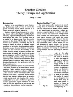
Snubber Circuits: Theory , Design and Application
www.ti.comSnubber Circuits: Theory , Design and Application Philip C. Todd Passive Snubber Types The basic function of a snubber is to absorb energy from the reactances in the power circuit. The fIrst classification of snubber circuits is wheth-er they absorb energy in …

Snubber Circuits Suppress Voltage Transient Spikes in ...
pdfserv.maximintegrated.comThe damping of the resonant circuit should be optimized as excessive damping can also lead to increased switching times and result in increased losses. A snubber could therefore be used to clamp the voltage spike or damp the ringing to reduce noise in the system or both.
DC/AC Pure Sine Wave Inverter
web.wpi.eduapplication of a steady constant voltage across a circuit resulting in a constant current. A battery is the most common source of DC transmission as …