Transformer Winding
Found 8 free book(s)
Guide to Transformer Resistance Testing 100406
portalvhds963slh4m3fqg2.blob.core.windows.netA Guide to Transformer Winding Resistance Measurements Bruce Hembroff, CET, Manitoba Hydro Matz Ohlen, Megger Sweden Peter Werelius, Megger Sweden Abstract: Measuring a transformer's DC resistance from one external terminal to another can reveal a great deal of information about the transformer. In addition to the obvious faulted winding (i.e., an
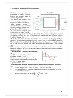
1. Explain the Working principle of transformer
www.khitguntur.ac.in1. When an alternating current is supplied to the primary windings of the transformer, it generates an alternating magnetic flux in the winding which is then induced in the secondary winding also through Faraday’s law of electromagnetic induction, and is then transferred to the externally connected load. 2.

Snubber Circuits Suppress Voltage Transient Spikes in ...
pdfserv.maximintegrated.comelements in the transformer and the switch determine the magnitude of this voltage spike. At high output voltagesthe circuit parasitics become large relative to the amount of output power delivered. The primary leakage inductance, LLP, and the primary winding capacitance in the transformer, CP, and

Power Transformer Factory Test using IEEE Standards
r5.ieee.orgPower Transformer Factory Test using IEEE Standards Waldemar Ziomek CG Power Systems Canada IEEE Training, Houston, Texas, Oct.8-9, 2014 ... Winding Insulation resistance X Quality Core/clamp insulation resistance X Quality Ratio test X Quality and performance

'Magnetics Design 5 - Inductor and Flyback Transformer …
www.ti.comnition). However, the current in each winding of any flyback transformer is always highly discontinuous, regardless of inductor current mode. This is because current ( ampere-turns ) transfers back and forth be-tween primary and secondary(s) at the switching fre-quency. As shown in Fig. 5-3, the current in each

Back to the Basics Current Testing - Valence Electrical
relaytraining.comhave a physical primary winding and are considered to have one primary turn. When current flows through the primary winding, the following actions occur: The iron core inside the transformer is magnetized. The magnetized iron core induces a voltage in the secondary coils.
EE 340 Spring 2011 - UNLV
www.egr.unlv.eduapplied to the rotor winding producing a rotor magnetic field. The rotor is then turned by external means producing a rotating magnetic field, which induces a 3-phase voltage within the stator winding. • Field windings are the windings producing the main magnetic field (rotor windings • armature windings are the windings
Instrument Transformers Application Guide
library.e.abb.comA current transformer is ideally a short-circuited transformer where the secondary ter-minal voltage is zero and the magnetizing current is negligible. Voltage transformers For a transformer in no load the following is valid: 1 2 1 2 This equation gives voltage transformation in proportion to the primary and secondary turns.