Search results with tag "Inductors"
Chapter 3: Capacitors, Inductors, and Complex Impedance
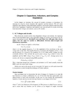
physics.wm.eduChapter 3: Capacitors, Inductors, and Complex Impedance In this chapter we introduce the concept of complex resistance, or impedance, by studying two reactive circuit elements, the capacitor and the inductor. We will study capacitors and inductors using differential equations and Fourier analysis and from these derive their impedance.

SMD Power Inductors - AVX Corporation
catalogs.kyocera-avx.comLMax SMD Power Inductor LMXN Series – Non-Shielded Style C FEATURES • High power, High saturation inductors • Ideal inductors for DC-DC converters in notebook computers, PDAs, Step-up or step-down converters, flash memory programmers, etc. • 0705 has ceramic base with gold-plating • Others have LCP plastic base APPLICATIONS

Mutually coupled inductors. Coupling coefficient. Power ...
www.uni-ruse.bgPower and energy of mutually coupled inductors. Analysis of circuits with mutually coupled inductor. 6.1. Equivalent circuits of mutually coupled inductors As was already mentioned in the second topic, when the magnetic field of one coil reaches a second

Capacitor and inductors - MIT OpenCourseWare
ocw.mit.eduto circuits that contain capacitors and inductors. Unlike the resistor which dissipates energy, ideal capacitors and inductors store energy rather than dissipating it. Capacitor: In both digital and analog electronic circuits a capacitor is a fundamental element. It enables the filtering of signals and it provides a fundamental memory element.

RLC transients - Iowa State University
tuttle.merc.iastate.eduand inductors together, a transient also occurs. With some differences: • Energy stored in capacitors (electric fields) and inductors (magnetic fields) can trade back and forth during the transient, leading to possible “ringing” effects. • The transient waveform can be quite different, depending on the
Chapter 31 Alternating Current Circuits
www.austincc.eduAverage Power - Inductors Inductors don’t dissipate energy, they store energy. The voltage and the current are out of phase by 90 o. As we saw with Work, energy changed only when a portion of the force was in the direction of the displacement. In electrical circuits energy is dissipated only if a portion of the voltage is in phase with the ...

AN-1197Selecting Inductors for Buck Converters
www.ti.comNow, for a buck regulator, we can show that the duty cycle is: (5) where VD is the forward drop across the catch diode (≅0.5V for a Schottky diode). ‘r' can be finally written as: (6) and L is therefore: (7) where f is in Hz. SNVA038B– May 2001– Revised April 2013 AN-1197Selecting Inductors for Buck Converters 3 Submit Documentation ...

Chapter 5 – Impedance Matching and Tuning - ITTC
www.ittc.ku.eduExamples of reactive elements include inductors, capacitors, transformers, as well as lengths of lossless transmission lines. Thus, constructing a proper lossless matching network will lead to the happy condition where: PP P Lin= = avl * Note that the design and construction of this lossless network will depend on both the value of source ...
Chapter 9 AC Sweep and Signal Analysis - UWECE
class.ece.uw.eduYL = 1/jωL for inductors Star-Hspice allows resistors to have different DC and AC values. If AC=<value> is specified in a resistor statement, the operating point is calculated using the DC value of resistance, but the AC resistance value is used in the AC analysis. This is convenient when analyzing operational amplifiers, since the operating point

IS 2026-1 (2011): Power transformers, Part 1: General
law.resource.org60310 : 2004 Railway applications — Traction transformers and inductors on board rolling stock 60068-3-3 : 1991 Environmental testing — Part 3: Guidance, seismic test methods for equipment For the purpose of deciding whether a particular requirement of this standard is …

17: Transmission Lines - Imperial College London
www.ee.ic.ac.ukWe represent as a large number of small inductors and capacitors spaced along the line. The signal speed along a transmisison line is predictable. Transmission Line Equations + 17: Transmission Lines

Designing DC/DC converters based on ZETA topology
www.ti.comThe ZETA converter also needs two inductors and a series capacitor, sometimes called a flying capacitor. ... steady-state peak current in the high-side inductor, as ... The power FET’s current rating will determine the ZETA converter’s maxi-

POWER INDUCTOR OVERVIEW - Pulse Electronics
www.pulseelectronics.com• AC core and AC conductor loss calculation to verify thermals and efficiency. Pulse Power Inductors come in a wide-range of product technologies including power beads, molded, composite, round wire coils, drum cores, flat wire, planar and toroids. Offerings range from a few mA to 150Apk, from 20nH to 10mH in both surface mount and through-hole

AN136 - PCB Layout Considerations for Non-Isolated ...
www.analog.comFigure 3. Minimize the High di/dt Loop Area in the Synchronous Buck Converter. (a) High di/dt loop (Hot Loop) and its Parasitic PCB Inductors, (b) Layout Example Figure 2. Continuous and Pulsating Current Paths of a Synchronous Buck Converter ESROUT RVOUT + COUT – CHF QT QB D ESRIN CIN VIN+ VIN +– SW PGND HIGH dV/dt NODE LF CONTINUE CURRENT ...
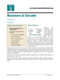
Resistors & Circuits
www.learnabout-electronics.orgFig.2.0.2). Wirewound resistors however, do not not have the close tolerance of composition or film types. This 4R7 resistor has a tolerance of ±10%. Wirewound resistors usually have a resistance range from around 1 Ω to about 50K Ω. Because they use a coil of wire as their resistive element they tend to act as inductors to some degree. This ...

'Magnetics Design 5 - Inductor and Flyback Transformer …
www.ti.comous mode, with significant core loss, total loss is at a broad minimum when core and winding losses are approximately equal. But when inductors are de-signed for the continuo~s mode, core loss is often negligible, so that the t~talloss limit can be allocated entirely to the windings. General Considerations --Core

Voltage/Current Phase Angle
www.philsherrod.comFor resistance, and , so Power Factor = 1 For pure capacitance or inductance, and , so Power Factor = 0 In other words, inductors and capacitors don’t dissipate power – they store it. So power is dissipated only by current flowing through resistors. Power with resistance load Power with pure inductance or capacitance
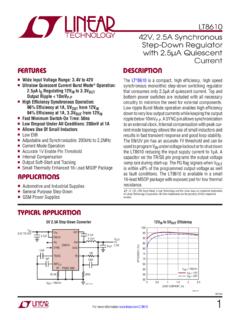
LT8610 - 42V, 2.5A Synchronous Step-Down Regulator with 2 ...
www.analog.comrent mode topology allows the use of small inductors and results in fast transient response and good loop stability. The EN/UV pin has an accurate 1V threshold and can be used to program VIN undervoltage lockout or to shut down the LT8610 reducing the input supply current to 1µA. A capacitor on the TR/SS pin programs the output voltage
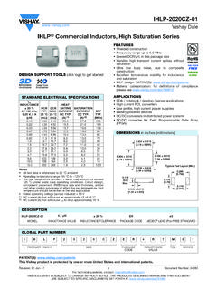
IHLP-2020CZ-01
www.vishay.comIHLP® Commercial Inductors, High Saturation Series DESIGN SUPPORT TOOLS click logo to get started Notes • All test data is referenced to 25 °C ambient • Operating temperature range -55 °C to +125 °C • The part temperature (ambient + temp. rise) should not exceed 125 °C under worst case operating conditions. Circuit design,

How to create a transformer using LTSpice
web.cecs.pdx.eduStep 1) You need two inductors. Change inductor names as Lp and Ls. Right click on L1 and change it to Lp and repeat same process for L2. → Step 2) Right click on Lp and L2s to open inductor properties window. Step 3) This is an optional step. We will rotate Ls to get a better look for our transformer.

How does it Work? Common Mode Chokes - Pulse Electronics
www.pulseelectronics.comportion consists of differential mode inductors and the Common Mode Choke (CMC) or Current Compensation Choke and along with the capacitors form a network of L-C filters. To understand how a CMC works, one must first understand the difference between common mode noise and differential mode noise.

CUSTOMS TARIFF - SCHEDULE 85 i- Chapter 85 ELECTRICAL ...
cbsa-asfc.gc.ca85.41, or inductors classifiable under heading 85.04, formed to all intents and purposes indivisibly into a single body like an integrated circuit, as a component of a kind used for assembly onto a printed circuit board (PCB) or other carrier, through the connecting of pins, leads, balls, lands, bumps, or pads. For the purpose of this definition:

Chapter 31 – Alternating Current - Physics Main
physics.ucf.edu- Power in Alternating-Current Circuits - Resonance in Alternating-Current Circuits - Transformers. 1. Phasors and Alternating Currents ... Inductors used to block high ω ...

Simulating a switch mode power supply with LTspice
www.cm.ph.bham.ac.ukElectronics Simulating a switch mode power supply - LTspice conversions that the phone may need to power its display (˘10 V) and its processor (˘1 V) from its nom-inally 3.7 V battery. In this section, you will investigate how this is done using inductors and electronic switches. 3.1 Inductor and Switch Consider the circuit of Fig. 4.

LM2576 - 3.0 A, 15 V, Step-Down Switching Regulator
www.onsemi.cominductors optimized for use with the LM2576 are offered by several different inductor manufacturers. Since the LM2576 converter is a switch−mode power supply, its efficiency is significantly higher in comparison with popular three−terminal linear regulators, especially with higher input voltages.

Determining Inductor Power Losses - Mouser Electronics
www.mouser.comdetermining inductor power loss. It also discussed the importance of knowing where inductor power losses come from in order to reduce heat creation and thus improve overall efficiency. For a more thorough discussion on ac losses refer to: Document 1400, titled Choosing Inductors for Energy Efficient Power Applications. Determining Inductor
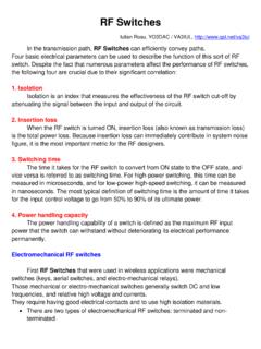
RF Switches - QSL.net
www.qsl.netOther chip components like capacitors, inductors, and resistors are independently ... Absorptive switch will have a good VSWR on each port regardless the switch mode. • Reflective switches leave the unused port un-terminated. In a reflective switch, the impedance of the port that is OFF will not be 50 Ω and will ...

Inductors & Inductance - Cleveland Institute of Electronics
cie-wc.eduInductors & Inductance Identical inductances in series If two inductors are placed in series, any current that passes through the combined double inductor must pass through both its parts. Thus by the definition of inductance, the inductance is doubled as well. In general, inductances in series add, just like resistances.

An introduction to anaesthesia - University College London
www.ucl.ac.ukThis introduc-tion to the components of an anaesthetic will help readers to get more from clinical attachments in surgery and anaesthetics or serve as an introduction to the topic for novice or non-anaesthetists. Types and sites of anaesthesia The term anaesthesia comes from the
Flyback transformer design considerations for efficiency ...
www.ti.comThe flyback topology The flyback transformer is not really a transformer in the conventional sense; it is actually a coupled inductor. Figure 1 is a simplified schematic of a flyback converter. The flyback transformer in this example has three windings: primary, secondary and bias (sometimes called the auxiliary winding).

DESIGN AND IMPLEMENTATION OF SYNCHRONOUS …
ethesis.nitrkl.ac.in4.3 Synchronous Buck Converter 52 4.3.1 MOSFET (IRF540N) 53 4.3.2 Capacitor Design 54 4.3.3 Schottky Diode (D) 54 4.3.4 Inductor Design 54 4.3.5 Experimental Setup 56 4.4 Charging circuit 56 4.5 Pulse Generator Circuit
Drive circuits for Power MOSFETs and IGBTs
www.st.comTRIAC requires a series inductor for EMI filtering. When the power is controlled by an IGBT, the switching behaviour can be softened at both turn-on and turn-off so that the inductor is no longer required. The switching losses incurred by slowing down the turn-off of the IGBT are not critical at mains frequency.
EMI Noise Reduction Techniques for High Frequency Power ...
vtechworks.lib.vt.eduinductor is integrate into PCB winding for the first time. Furthermore, balance technique is applied to reduce CM noise for PFC converter. With PCB winding, the balance technique has better high frequency performance. The PCB winding inductor can achieve high power density, high efficiency and automated manufacture.

Drafting Symbols - G-W Learning
www.g-wlearning.comMagnetic Core Shielded Transformer, Magnetic Core Auto-Transformer, Adjustable Circuit Breaker Twin Triode Using Elongated Envelope Voltage Regulator, also, Glow Lamp Phototube Inductor, Winding, Reactor, General Magnetic Core Inductor Adjustable Inductor Ballast Lamp Fluorescent, 2-Terminal Lamp Incandescent Lamp Ground Chassis Ground ...
12. Transformers, Impedance Matching and Maximum Power ...
www.hunter.cuny.eduscope, you measure the voltage across the inductor because the other wire need in the circuit is the ground. This arrangement is unsatisfactory since if you want to measure the voltage across the resistor R, you must interchange the resistor R and inductor L in the above circuit and then attach the oscilloscope probe to the top of the resistor.

Switching regulator fundamentals (Rev. C) - Texas …
www.ti.comBuck Regulator Inductor Current As explained, the current through the inductor ramps up when the switch is on, and ramps down when the switch is off. The DC load current from the regulated output is the average value of the inductor current. The peak-to-peak difference in the inductor current waveform is referred to as the inductor ripple current,

DC/DC Buck-Boost Converter Efficiency and Power ...
www.jmest.orgDC buck-boost converter Fig.1, the equivalent circuit of the buck-boost converter with parasitic resistances is used, as shown in Fig. 2, where R s is the equivalent resistance of the MOSFET during the ON-State period, r is the inductor equivalent series resistance, r C is the capacitor equivalent series resistance, R D

B. Practical Issues for L and C
www.engr.colostate.edu2. DC Current Operating Point in a Buck-boost circuit via Capacitor charge balance We will show below by separate calculation that I L = I o + I in. I C-V o /R DT s D'T s t i C + i R = 0-I L - V o /R i C + i L + i R = 0 We find that the inductor current is: I V L RD ≡ − o ' and / or I V D D R L ≡ g ( ')2 Example: V o = -20V, V g = 30V and ...
Sepic Converter Design and Operation
web.wpi.eduMay 01, 2014 · Buck-boost converters can be cheaper because they only require a single inductor and a capacitor. However, these converters suffer from a high amount of input current ripple. This ripple can create harmonics; in many applications these harmonics necessitate using a large capacitor or an LC filter. This often makes the buck-boost expensive or

Power MOSFET Selection Guide - NXP
www.nxp.comHigh Switching Frequencies Low Spiking Thermal Efficiency Low Leakage Specialist High Sides Improved Safe Operating Area Increasing switching frequency from 300KHz to 1MHz allows a 70 - 80% reduction in inductor size. NextPowerS3’s excellent switching performance enables such design choices with minimal loss of efficiency. Thanks to optimised ...
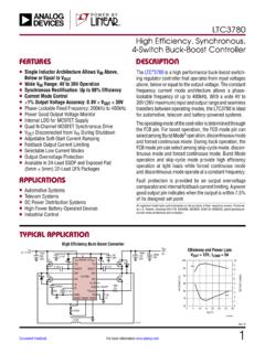
LTC3780 (Rev G) - Analog Devices
www.analog.comHigh Efficiency Buck-Boost Converter n Single Inductor Architecture Allows VIN Above, Below or Equal to VOUT n Wide VIN Range: 4V to 36V Operation n Synchronous Rectification: Up to 98% Efficiency n Current Mode Control n ±1% Output Voltage Accuracy: 0.8V < VOUT < 30V n Phase-Lockable Fixed Frequency: 200kHz to 400kHz n Power Good Output ...
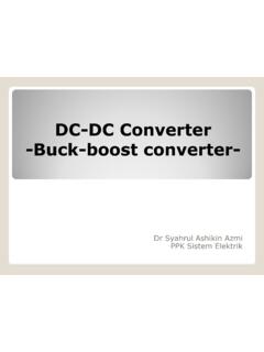
DC-DC Converter -Buck-boost converter- - …
www.123seminarsonly.cominductor when compared to boost and buck-boost. Boost ... efficiency decreases. •Furthermore, there is no isolation between the input and output voltage, which is a highly desirable criteria in most application. •For high-power applications, multistage conversions are used, where a dc voltage is converted to ac by an inverter. The ac output ...
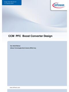
CCM PFC Boost Converter Design - Mouser Electronics
www.mouser.commore. For that reason the buck converter is eliminated, and the buck-boost converter has high switch voltage stress (Vin+Vo). Moreover, the boost converter has the filter inductor on the input side, which provides a smooth continuous input current waveform as opposed to the discontinuous input current of a buck or buck-boost topology.

Forward Converter Design Note - Mouser Electronics
www.mouser.comThe transformer can thus be made more ideal with much higher magnetizing inductance and no air gap. The resulting lower peak currents in primary as well as secondary means lower copper losses compared to Flyback. 2. Filtered output: the output inductor and freewheeling diode keeps the output current fairly constant and
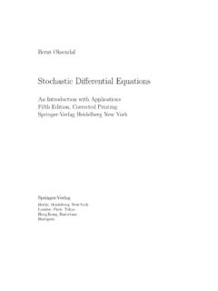
Stochastic Difierential Equations
www.stat.ucla.eduthe stochastic calculus. Problem 4 is the Dirichlet problem. Although this is purely deterministic we outline in Chapters VII and VIII how the introduc-tion of an associated Ito difiusion (i.e. solution of a stochastic difierential equation) leads to a simple, intuitive and useful stochastic solution, which is

Complete Guide to Induction Coil Design
sg-induction.com4. The magnetic center of the inductor is not necessarily the geometric center. At the point where the leads and coil join, the magnetic field is weaker. This effect is most pronounced in single-turn coils. As the number of coil turns increases and the flux from each turn is added to that from the previous turns, this condition becomes less ...
Understanding Boost Power Stages in Switchmode Power …
www.ti.comA power stage can operate in continuous or discontinuous inductor current mode. In continuous inductor current mode, current flows continuously in the inductor during the entire switching cycle in steady-state operation. In discontinuous inductor current mode, inductor current is zero for a portion of the switching cycle.

Physics Notes for Class 12 chapter 6 ELECTROMAGNETIC I ...
ncerthelp.comIf core of the solenoid is of any other magnetic material, then L = μ o μ r N 2 A / l Self – inductance of a toroid L = μ o N2 A / 2πr Where, r = radius of the toroid Energy stored in an inductor E = 1 / 2 LI2 Mutual Induction The phenomena of production of induced emf in a circuit due to the change in magnetic flux in
Similar queries
Inductors, Power Inductors, Power, High power, High, Inductor, MIT OpenCourseWare, Inductors Inductors, Inductors for Buck Converters, Buck, Analysis, Current, POWER INDUCTOR OVERVIEW, Core, Wirewound, Inductor and Flyback Transformer, IHLP-2020CZ-01, How does it Work, Common Mode Chokes, Mode inductors, Common Mode Choke, Choke, Common mode, Mode, Simulating a switch mode power supply with LTspice, Simulating a switch mode power, Inductor power, Mouser Electronics, Inductors & Inductance, An introduction to anaesthesia, Introduc, Tion, An introduction, Flyback transformer design considerations for efficiency, Flyback, Flyback transformer, Transformer, DESIGN AND IMPLEMENTATION OF SYNCHRONOUS, Drive circuits for Power MOSFETs and, Drafting Symbols, Magnetic Core, Magnetic Core Inductor, Switching regulator fundamentals, Texas, Converter, Calculation, Single Inductor, Efficiency, Analog Devices, High Efficiency Buck, Buck-boost converter, CCM PFC Boost Converter Design, Stochastic Difierential Equations, Stochastic calculus, Introduc-tion, Stochastic, Complete Guide to Induction Coil Design, Magnetic