Magnetic Core Inductor
Found 8 free book(s)
Cleveland Institute of Electronics Electronics Symbols ...
www.cie-wc.edumagnetic optical shielding n— channel p- base shielded assembly shielded , twin lead 2 transistor photo — transistor pnp transistor pnpn transistor two gate ... air—core inductor —rrvn— adjustable inductor tapped inductor —rrm— inductor , iron-core , permanent magnet core (electromagnet) inductor , powdered iron-

Faraday's Law of Electromagnetic Induction
phaseback.comThe energy stored in an inductor is: In general, the energy density (energy per unit volume) in a magnetic field is: Transformers ... In a standard transformer, the two coils are usually wrapped around the same iron core, ensuring that the magnetic flux is the same through both coils. The coil that provides the flux (i.e., the coil connected to ...
Faraday’s Law Induction
mcba11.phys.unsw.edu.aumagnetic field – i.e. the change in the slope of the graph. The magnitude of the slope is largest at c. Points d and e are on a straight line, so the slope is the same at each point. ... placed around the iron core of an inductor are repelled upwards when a conductor is
LECTURE 34 HIGH FREQUENCY TRANSFORMER
www.engr.colostate.edumagnetic core and in small air gaps which arise when the separate core halves forming a closed magnetic loop core come together. In the equivalent circuit of a real transformer, mutual inductance appears in parallel with the primary windings only. The energy stored in the magnetization inductance is a function of the volt-seconds per turn

Complete Guide to Induction Coil Design
sg-induction.com4. The magnetic center of the inductor is not necessarily the geometric center. At the point where the leads and coil join, the magnetic field is weaker. This effect is most pronounced in single-turn coils. As the number of coil turns increases and the flux from each turn is added to that from the previous turns, this condition becomes less ...
Chapter 11 Inductance and Magnetic Energy
web.mit.eduInductance and Magnetic Energy 11.1 Mutual Inductance Suppose two coils are placed near each other, as shown in Figure 11.1.1 Figure 11.1.1 Changing current in coil 1 produces changing magnetic flux in coil 2. The first coil has N1 turns and carries a current I1 which gives rise to a magnetic field B1 G
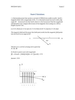
Exam2 solutions Fall11 - Department of Physics
www.phys.ufl.eduAt what value of x is the net magnetic field zero?((1) 3 (2) 1 (3) 0 (4) 5 (5) 7 S: Between two wires, magnetic field produced by I points into the page and magnetic field produced by 3I points out of the page. The net magnetic field is zero when the two fields have same magnitude. !!! 2!!−2 =!!3! 2!6−! Solve it to get x=3. (14.
12. Transformers, Impedance Matching and Maximum Power ...
www.hunter.cuny.eduscope, you measure the voltage across the inductor because the other wire need in the circuit is the ground. This arrangement is unsatisfactory since if you want to measure the voltage across the resistor R, you must interchange the resistor R and inductor L in the above circuit and then attach the oscilloscope probe to the top of the resistor.