Example: marketing
DESIGN AND IMPLEMENTATION OF SYNCHRONOUS …
4.3 Synchronous Buck Converter 52 4.3.1 MOSFET (IRF540N) 53 4.3.2 Capacitor Design 54 4.3.3 Schottky Diode (D) 54 4.3.4 Inductor Design 54 4.3.5 Experimental Setup 56 4.4 Charging circuit 56 4.5 Pulse Generator Circuit
Tags:
Information
Domain:
Source:
Link to this page:
Documents from same domain
Digital PID Controller Design for DC-DC Buck …
ethesis.nitrkl.ac.ini National Institute Of Technology, Rourkela Certificate This is to certify that the report entitled, “Digital PID controller Design for DC-DC Buck ...

Computer aided analysis and design of multi …
ethesis.nitrkl.ac.inComputer aided analysis and design of multi-storeyed buildings . A Project Submitted . In Partial Fulfilment of the Requirements . For the Degree of

Design of Water Tank
ethesis.nitrkl.ac.inA vi ABSTRACT Storage reservoirs and overhead tank are used to store water, liquid petroleum, petroleum products and similar liquids. The force analysis of
Modelling and Simulation of ethyl acetate reactive ...
ethesis.nitrkl.ac.inModelling and Simulation of ethyl acetate reactive distillation column using ASPEN PLUS A Project submitted to the National Institute of Technology, Rourkela
PROBLEMS AND CHALLENGES FACED BY URBAN …
ethesis.nitrkl.ac.inPROBLEMS AND CHALLENGES FACED BY URBAN WORKING WOMEN IN INDIA A Dissertation Submitted to the Department of Humanities and Social Sciences, National Institute of Technology Rourkela, in Partial Fulfillment of
V/f CONTROL OF INDUCTION MOTOR DRIVE - …
ethesis.nitrkl.ac.ini V/f CONTROL OF INDUCTION MOTOR DRIVE A Thesis submitted in partial fulfillment of the requirements for the degree of Bachelor of Technology in “Electrical Engineering”

Addiction to Technological Gadgets and Its Impact …
ethesis.nitrkl.ac.inAddiction to Technological Gadgets and Its Impact on Health and Lifestyle: A Study on College Students (Thesis submitted for the partial fulfilment of
GSM based Distribution Transformer Monitoring …
ethesis.nitrkl.ac.inii GSM based Distribution Transformer Monitoring System A THESIS IN PARTIAL FULFILMENTS OF REQUIREMENTS FOR THE AWARD …
SIMULATION OF HEAT TRANSFER - ethesis
ethesis.nitrkl.ac.in1 simulation of heat transfer phenomenon in furnace using fluent-gambit a thesis submitted in partial fulfillment of the requirements for the degree of
DESIGN OF WIRELESS WEATHER MONITORING …
ethesis.nitrkl.ac.inDESIGN OF WIRELESS WEATHER MONITORING SYSTEM Thesis submitted in partial fulfilment of the requirements for the degree of Bachelor of Technology
Related documents
Sepic Converter Design and Operation
web.wpi.eduMay 01, 2014 · Buck-boost converters can be cheaper because they only require a single inductor and a capacitor. However, these converters suffer from a high amount of input current ripple. This ripple can create harmonics; in many applications these harmonics necessitate using a large capacitor or an LC filter. This often makes the buck-boost expensive or

'Magnetics Design 5 - Inductor and Flyback Transformer …
www.ti.comOutput filter inductor (buck-derived) Boost inductor Flyback (buck-boost) inductor Input filter inductor.Multiple winding inductors: Coupled output filter inductor (R5) Flyback transformer Inductor design also depends greatly on the in-ductor current operating mode (Figure 5-2):.Discontinuous inductor current mode. when the

Switching regulator fundamentals (Rev. C) - Texas …
www.ti.comBuck Regulator Inductor Current As explained, the current through the inductor ramps up when the switch is on, and ramps down when the switch is off. The DC load current from the regulated output is the average value of the inductor current. The peak-to-peak difference in the inductor current waveform is referred to as the inductor ripple current,

POWER CONVERTER TOPOLOGY TRENDS - PSMA
www.psma.comSINGLE-ENDED FLYBACK BOOST BUCK-BOOST BUCK ACTIVE CLAMP 2-SWITCH LLC. Isolated Power Topology Derivatives 8 “Mainstream” Converter Topologies Non-Isolated 1. Boost 4. 2. Buck-Boost 5. 3. Buck 6. Isolated Flyback Forward Push-Pull 7. Half Bridge 8. Full Bridge. Power levels numbers for general . discussion only. Exceptions aplenty.
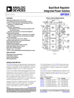
Quad Buck Regulator Integrated Power Solution Data Sheet ...
www.analog.comProgrammable 2 A/4 A/6 A sync buck regulators with low-side FET drivers Channel 3 and Channel 4: 2.5 A sync buck regulators Flexible parallel operation Single 12 A output (Channel 1 and Channel 2 in parallel) Single 5 A output (Channel 3 and Channel 4 in parallel) Low 1/f noise density 40 μV rms at 0.8 V REF for 10 Hz to 100 kHz
DC-DC Converter -Buck-boost converter- - …
www.123seminarsonly.comD < 0.5 = buck D = unity gain = 1 •This converter combine the capabilities of buck and boost converter. •Noted that the source is never connected directly to the load. Energy is stored in the inductor when the switch is on and transferred to the load when the switch is off. •Buck-boost converter is also called as indirect converter.
CCM PFC Boost Converter Design - Mouser Electronics
www.mouser.commore. For that reason the buck converter is eliminated, and the buck-boost converter has high switch voltage stress (Vin+Vo). Moreover, the boost converter has the filter inductor on the input side, which provides a smooth continuous input current waveform as opposed to the discontinuous input current of a buck or buck-boost topology.

Topologies for switch mode power supplies
www.st.coma. Single switch versus double switch flyback In the single switch flyback, an overvoltage spike is applied across the power switch at each turn off. The peak value of this overvoltage depends upon the switching time, the circuit capacitance and the primary to secondary transformer leakage inductance. So, a single switch flyback nearly always