Transcription of CCM PFC Boost Converter Design - Mouser Electronics
1 Design Note DN 2013-01 January 2013 CCM PFC Boost Converter Design Sam Abdel-Rahman Infineon Technologies North America (IFNA) Corp. CCM PFC Boost Converter Design 2 Design Note DN 2013-01 January 2013 Edition 2013-01-01 Published by Infineon Technologies North America 27703 Emperor Blvd, suite 310, Durham, NC 27703 Infineon Technologies North America Corp. 2013 All Rights Reserved. Attention please! THE INFORMATION GIVEN IN THIS APPLICATION NOTE IS GIVEN AS A HINT FOR THE IMPLEMEN-TATION OF THE INFINEON TECHNOLOGIES COMPONENT ONLY AND SHALL NOT BE REGARDED AS ANY DESCRIPTION OR WARRANTY OF A CERTAIN FUNCTIONALITY, CONDITION OR QUALITY OF THE INFINEON TECHNOLOGIES COMPONENT.
2 THE RECIPIENT OF THIS APPLICATION NOTE MUST VERIFY ANY FUNCTION DESCRIBED HEREIN IN THE REAL APPLICATION. INFINEON TECHNOLOGIES HEREBY DISCLAIMS ANY AND ALL WARRANTIES AND LIABILITIES OF ANY KIND (INCLUDING WITHOUT LIMITATION WARRANTIES OF NON-INFRINGEMENT OF INTELLECTUAL PROPERTY RIGHTS OF ANY THIRD PARTY) WITH RESPECT TO ANY AND ALL INFORMATION GIVEN IN THIS APPLICATION NOTE. Information For further information on technology, delivery terms and conditions and prices please contact your nearest Infineon Technologies Office ( ).
3 Warnings Due to technical requirements components may contain dangerous substances. For information on the types in question please contact your nearest Infineon Technologies Office. Infineon Technologies Components may only be used in life-support devices or systems with the express written approval of Infineon Technologies, if a failure of such components can reasonably be expected to cause the failure of that life-support device or system, or to affect the safety or effectiveness of that device or system. Life support devices or systems are intended to be implanted in the human body, or to support and/or maintain and sustain and/or protect human life.
4 If they fail, it is reasonable to assume that the health of the user or other persons may be endangered. DN 2013-01 Subjects: CCM PFC Boost Converter Design Author: Sam Abdel-Rahman (IFNA PMM SMD AMR PMD 2) We Listen to Your Comments Any information within this document that you feel is wrong, unclear or missing at all? Your feedback will help us to continuously improve the quality of this document. Please send your proposal (including a reference to this document) to: CCM PFC Boost Converter Design 3 Design Note DN 2013-01 January 2013 Table of contents 1 Introduction.
5 4 2 Boost topology .. 4 3 PFC Modes of Operation .. 5 4 CCM PFC Boost Design Equations .. 7 5 References .. 17 CCM PFC Boost Converter Design 4 Design Note DN 2013-01 January 2013 1 Introduction Power Factor Correction (PFC) shapes the input current of the power supply to be in synchronization with the mains voltage, in order to maximize the real power drawn from the mains. In a perfect PFC circuit, the input current follows the input voltage as would an equivalent resistor, with no added input current harmonics. This document is intended to discuss the topology and operational mode for high power PFC applications (>300W), and provide detailed Design equations with examples.
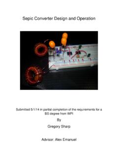
6 2 Boost topology Although active PFC can be achieved by any basic topology, the Boost Converter (Figure ) is the most popular topology used in PFC applications, for the following reasons: The line voltage varies from zero to some peak value typically 375V, hence; a step up Converter is needed to output a dc bus voltage of 380V or more. For that reason the buck Converter is eliminated, and the buck - Boost Converter has high switch voltage stress (Vin+Vo). Moreover, the Boost Converter has the filter inductor on the input side, which provides a smooth continuous input current waveform as opposed to the discontinuous input current of a buck or buck - Boost topology.
7 This continuous input current is much easier to filer, which is a major advantage because any additional filtering that is needed on the input side of the Converter adds cost and reduces the power factor due to capacitive loading of the line. Boost Key Waveforms Figure ACPFC ConverterDC/DC ConverterLoadDC BusVacACLDRoVacCoS+Vo-DC BusSV_LI_LI_SI_DT=1/fDTVinVin-VoI_LmaxI_ LminI_LmaxI_LmaxI_LminCCM PFC Boost Converter Design 5 Design Note DN 2013-01 January 2013 3 PFC Modes of Operation The Boost Converter can operate in three modes: continuous conduction mode (CCM), discontinuous conduction mode (DCM), and critical conduction mode (CrCM).
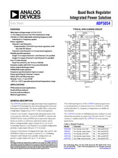
8 Fig. 2 shows modeled waveforms to illustrate the inductor and input currents in the three operating modes, for the same exact voltage and power conditions. 01104- 2104- 3104- 4104- 051015 Iint()ILt()tContinuous Conduction Mode (CCM) 01104- 2104- 3104- 4104- 051015 Iint()ILt()tDiscontinuous Conduction Mode (DCM) Figure Although DCM operation seems simpler than CrCM, since it may operate in constant frequency operation, DCM has the disadvantage that it has the highest peak current compared to CCM and CrCM, but with no performance advantage compared to CrCM, and one potential disadvantage.
9 For that reason, CrCM is a more common practice than DCM, therefore, this document will exclude the DCM mode. CrCM may be considered a special case of CCM, where operation is controlled to stay at the boundary between CCM and DCM. CrCM usually uses constant on-time control; as the line voltage is changing across the 60Hz line cycle, the reset time for the Boost inductor varies, and the operating frequency will change as well in order while maintaining boundary mode operation. CrCM dedicated controllers sense the inductor current zero crossing in order to trigger the start of the next switching cycle.
10 When carefully designed, the Boost rectifier diode for the CrCM PFC is selected not to be ultra-fast, but of medium fast speed, so that the inductor current not only completely resets to zero but may switch slightly negative. This energy stored in the CrCM Boost inductor will Flyback to ground, achieving ZVS turn-on for the Boost MOSFET under most conditions, particularly at input voltage above 200V, when this will not usually occur for a 400V nominal bulk bus system. The current ripple (or the peak current) in CrCM is twice the average value, which greatly increases the RMS currents and turn off current.