
100-002 Engine Diagrams - JustAnswer
Nov 06, 2010 · 14. Fuel lift pump (behind ECM cooling plate) 15. Fuel inlet connection 16. Fuel return from injector 17. Fuel supply to lift pump 18. Fuel return from fuel rail pressure relief valve 19. Fuel return from high pressure fuel pump 20. Crankshaft speed sensor 21. Camshaft speed sensor 22. Oil pressure sensor 23. Fuel pump 24. Fuel cooler 25. Sea ...
Download 100-002 Engine Diagrams - JustAnswer

Information
Domain:
Source:
Link to this page:
Documents from same domain
Diagnostic Code Information for Caterpillar …
ww2.justanswer.comFeb 21, 2013 · Special Instruction Diagnostic Code Information for Caterpillar Electronic Control{1901, 1927, 1948, 3168, 4348, 4802, 4808, 4810, 5511, 5701, 7490, 7494, 7601, 7602, 7610, 7610,
Eaton Fuller Pull-Type Clutches 25 - JustAnswer
ww2.justanswer.comNov 03, 2011 · Eaton ® Fuller® Easy-Pedal ... Eaton Fuller Pull-Type Clutches 25.01 Clutch Adjustments Business Class Trucks Service Manual…

Eaton Fuller Automated Transmissions - JustAnswer
ww2.justanswer.comJan 25, 2010 · Eaton ®Fuller® Automated Transmissions ... Service Manual Eaton TRSM-0062 AutoShift Driver Instructions Eaton …
J1939 Datalink Diagnostics 54-133 - JustAnswer
ww2.justanswer.comAug 02, 2012 · J1939 Datalink Diagnostics 54-133 FLA COE > FLB COE ... disconnect the J1939 wiring inside the cab where it goes through the frontwall to the engine
TORQUE SPECIFICATIONS - JustAnswer
ww2.justanswer.comJun 14, 2009 · TORQUE SPECIFICATIONS (7.4L) Rocker Arm 4.3L With Press-In Studs Rocker Stud 35 (47) Rocker Nut 18 (25) 4.3L With Screw-In Studs Rocker Stud 35 (47)
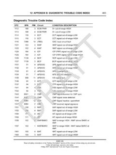
Diagnostic Trouble Code Index - JustAnswer - …
ww2.justanswer.comJan 28, 2013 · 466 12 APPENDIX B: DIAGNOSTIC TROUBLE CODE INDEX 1178 7316 0 VGT VGTactuatortemperatureabovehighlimit 1181 105 10 MAT MATstuckin-rangefault 1211 100 4 EOP ...

Unfiled Notes Page 1 - JustAnswer
ww2.justanswer.comSep 26, 2009 · 4. Check the cranking load of the window assembly in area W. If the window assembly binds, or the motor load sounds excessive, re-adjust the window assembly by correcting the channel

Unfiled Notes Page 1 - ww2.justanswer.com
ww2.justanswer.comOct 30, 2009 · Unfiled Notes Page 1 . Unfiled Notes Page 2 . Unfiled Notes Page 3 . 1.5 CENTRAL DOOR LOCKING NOTE: The circuit diagrams shown in this General Information Section are to aid in interpreting the operation of the circuit and only the main connectors and wiring colours are shown. For complete circuit details, refer to the …
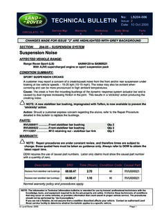
No: LS204-006 TECHNICAL BULLETIN Issue: 2
ww2.justanswer.comJul 03, 2010 · GTR Home > NAS > Service Information/ LS-Range Rover Sport/2006 > Workshop Manuals > Range Rover Sport Workshop Manual > Bookmark "204-06 Ride and Handing Optimization" > Link "Pipe Assembly/Rear Stabilizer Bar Bushing"

Parking Brake Actuator - 4.0L / 4.4L Service Repair No - 70.35
ww2.justanswer.comOct 01, 2010 · ALLDATA Online - 2006 Land Rover Range Rover Sport (LS) V8 -4394cc 4.4L - Servic ... Page 1 of 10 ... 10/1/2010. 9. Remove the LH rear brake disc. Remove the screw. 10. Disconnect both parking brake cables from the wheel hubs. Fully loosen the nut. Release the cable from the lower arm.
Related documents

Basic Lift Pump Installation - Kennedy Diesel
www.kennedydiesel.comBasic Lift Pump Installation Fuel tank removal is shown for pictorial aid only. Twin pump and single pump installation is the same as is the Pump filter combo. Installing lift supply pumps on a Duramax is a very straight forward procedure. This guide will cover using basic ½” …

Boom Lift Models 450A Series II 450AJ Series II 510AJ
manuals2.jlg.com3121179 – JLG Lift – a FOREWORD This manual is a very important tool! Keep it with the machine at all times. The purpose of this manual is to provide owners, users, operators, lessors, and lessees with the precautions and operating procedures essential for the safe and proper machine operation for its intended purpose.
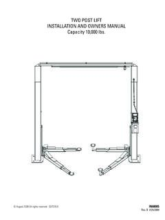
TWO POST LIFT INSTALLATION AND OWNERS MANUAL …
www.derekweaver.com2. This lift is designed for indoor use only, and should not be installed in a pit or depression. 3. The floor on which the lift is to be installed must be 4-¼” inch minimum thickness concrete, with a mini mum compressive strength of 3000 psi, and reinforced with steel bar. 4.

Installation, Operation and Maintenance Instructions
www.gouldspumps.com1.4 General precautions. WARNING: A pump is a pressure vessel with rotating parts that can be hazardous. Hazardous fluids may be contained by the pump including high temperature, flammable, acidic, caustic, explosive,

Calculating the Pump Head - Amick Racing
www.hvac.amickracing.comRemember that the static head is the difference in height that the pump will be required to provide. In the drawing below, showing a cooling tower, the static height might appear to be 40’. However, the water level in the tower sump is 28’ above the pump, so the pump must only provide a net lift of 12’. Therefore, the static head is 12’.

Split System Heat Pump Product Data - Trane
www.trane.com1 Certified in accordance with the Air-Source Unitary Heat Pump equipment certification program which is based on ARI Standard 210/240. 2 Calculated in accordance with N.E.C. Only use HACR circuit breakers or fuses. 3 Standard line lengths - 60'. Standard lift - 60' Suction and Liquid line.